
The flow rate and pressure relationship formula helps us understand how fluids move through piping systems. We see this relationship every day, but its practical implications can be tricky to understand. The flow rate connects directly to the square root of pressure difference. This means tiny changes in pressure can affect fluid movement through pipes by a lot.
Looking at fluid dynamics, the flow rate equation and formula give us a clear picture of pipe and channel behavior. Bernoulli’s equation shows an interesting pattern – higher flow rates lead to lower pressure. Poiseuille’s law tells us something fascinating too. The flow rate changes with the fourth power of pipe diameter. This becomes crucial knowledge for anyone who designs or fixes fluid systems.
Let’s break these complex formulas into bite-sized concepts. You’ll learn to calculate flow rate from pressure and see ground applications in industries of all types. The examples will show why tracking these measurements matters to keep systems safe and efficient.
What Are Flow Rate and Pressure?

Flow rate and pressure are the building blocks of fluid dynamics. These properties control how fluids move through pipes, channels, and systems we use every day.
Flow rate measures the volume of fluid that passes through a point in a specific time. This tells us how much fluid moves through a conduit – from water in pipes to oil in industrial systems. People measure flow rate in cubic meters per second (m³/s), though liters per minute or gallons per minute are common in everyday use.
Flow rate vs velocity
Flow rate and velocity might seem similar, but they’re quite different concepts that work together. Flow rate shows the amount of fluid passing through an area, while velocity shows the speed of that fluid’s movement in one direction.
This simple equation shows how they relate:
Q represents flow rate, A stands for cross-sectional area, and v is the fluid’s average velocity. The equation proves that in a pipe with steady flow rate, a smaller cross-sectional area means higher velocity. That’s why water shoots out faster when you partially cover a hose – the same amount of water must squeeze through a smaller opening.
Water and other incompressible fluids maintain constant flow rate throughout a pipe system. Scientists call this the continuity equation:
This means fluid speeds up in narrow sections and slows down in wider parts of the pipe.
Types of pressure in fluid systems
Pressure is simply force applied perpendicular to a surface per unit area. Fluid systems have several pressure types:
Static pressure – The pressure exerted by a fluid at rest, measured perpendicular to the fluid surface and independent of flow direction. For liquids, this is calculated as p = ρgh, where ρ is fluid density, g is gravity, and h is depth.
Dynamic pressure – The pressure resulting from fluid motion, calculated as p = ½ρv², where ρ is density and v is velocity. This pressure component increases with the square of velocity.
Total pressure – The sum of static and dynamic pressures, representing the fluid’s total energy at a point.
Absolute pressure – Pressure measured relative to a perfect vacuum.
Gauge pressure – Pressure measured relative to atmospheric pressure, which can be positive or negative.
Differential pressure – The difference in pressure between two points in a system.
Why understanding both is essential
Flow rate and pressure have a crucial relationship. Higher pressure typically means increased flow rate in most systems. This affects everything from your home’s plumbing to industrial processes.
Engineers use pressure and flow rate calculations to design systems that save energy. Systems with greater pressure drops need more powerful pumps or motors to keep the flow constant.
These measurements help spot problems like leaks, blockages, or poor performance quickly. Water treatment plants and pharmaceutical companies rely on exact pressure-flow relationships to maintain quality and safety standards.
Once you learn these concepts, you’ll understand advanced fluid dynamics better and make smarter decisions about system design and troubleshooting.
How Flow Rate and Pressure Interact
Fluid dynamics reveals amazing patterns in how pressure and flow rate work together. These two properties affect each other in pipe systems in ways that might seem contradictory at first. The physics behind these interactions makes perfect sense once you get into it.
The direct and inverse relationships
Pressure and flow rate can show both direct and inverse relationships based on which part of the system you look at.
Flow rate and pressure difference share a direct relationship from a qualitative viewpoint. A pipe system with fixed dimensions shows higher flow rates with greater pressure differences between points. Poiseuille’s law captures this mathematically by stating that flow stays proportional to pressure difference.
Bernoulli’s principle tells a different story. The pressure at any point drops as flow rate (or fluid velocity) goes up. This explains why fast-moving fluids push less against pipe walls than slow-moving ones.
These relationships might seem to clash, but they describe different aspects of how fluids behave. Poiseuille’s law tells us how pressure difference creates flow. Bernoulli’s principle explains how speed changes local pressure.
Effect of pipe diameter and elevation
Pipe diameter plays a huge role in flow dynamics. Flow rate changes with the fourth power of pipe diameter. A pipe twice as wide can carry 16 times more flow! Small changes in pipe size can restrict flow dramatically.
Fluid must move faster through narrower pipes to keep the same volumetric flow rate. This speed increase leads to pressure drops, as Bernoulli’s equation predicts.
Height changes create predictable pressure patterns. Upward fluid flow shows these effects:
Higher points have lower pressure because less fluid sits above them
Each meter up reduces pressure by a fixed amount
Downward flow works the opposite way:
More fluid weight above means higher pressure
Pressure gain matches the drop in height exactly
The total height difference matters most in actual systems. A fluid moving from 2m to 5m height loses pressure equal to 3m of fluid head. The path between doesn’t matter.
Real-life examples of pressure-flow dynamics
These principles show up everywhere. Your garden hose demonstrates this perfectly. Cover part of the opening with your thumb and water sprays farther. The narrow passage speeds up water flow while dropping pressure.
Rivers tell the same story. Wide sections flow peacefully until canyon walls squeeze them, making water rush through faster. The continuity equation (A₁v₁ = A₂v₂) explains how flow stays the same across different widths.
Tall buildings often face water pressure problems on upper floors as water fights gravity. Engineers fix this by adding booster pumps that keep pressure steady throughout.
Industry makes good use of these relationships. Differential pressure flowmeters measure flow by watching how pressure drops when fluid passes through a narrow spot. The pressure drop matches the square of flow rate, letting engineers measure flow accurately without disrupting the system.
Engineers use this knowledge to design systems that save energy while working exactly as needed.
Key Formulas That Define the Relationship
Mathematical relationships are the foundations of fluid dynamics. Three key formulas describe how pressure and flow rate interact under different conditions.
Bernoulli’s equation simplified
Bernoulli’s principle establishes a fundamental relationship between pressure, velocity, and elevation. The principle states that the total energy in a fluid streamline stays constant. The standard equation is expressed as:
p + ½ρv² + ρgh = constant
The equation uses p for pressure, ρ for fluid density, v for velocity, g for gravitational acceleration, and h for height. This relationship shows that pressure must decrease when velocity increases to maintain energy balance.
Bernoulli’s equation becomes simpler in practical applications. The equation for horizontal pipes where elevation doesn’t change (h₁ = h₂) is:
p₁ + ½ρv₁² = p₂ + ½ρv₂²
This simplified version shows that fluid pressure drops as it accelerates through a constriction. Note that Bernoulli’s equation needs several conditions: steady-state flow, incompressible fluid, frictionless flow, and streamlined flow patterns.
Poiseuille’s law for viscous fluids
Poiseuille’s law focuses on viscous fluids in pipes, while Bernoulli’s equation works with ideal fluids. The formula reads:
Q = π(P₁ – P₂)r⁴ / 8μL
Q represents volumetric flow rate, P₁ and P₂ are pressures at pipe ends, r is pipe radius, μ is fluid viscosity, and L is pipe length.
Poiseuille’s law shows a remarkable fourth-power relationship with radius. A pipe with twice the radius can carry about 16 times more flow. The law also shows that higher pressure differences create greater flow rates.
The law works only under specific conditions. These include laminar flow (no turbulence), incompressible Newtonian fluids, and long, straight pipes.
Flow rate formula using cross-sectional area
The flow rate equation stands as the most simple yet crucial relationship. It connects velocity to cross-sectional area:
Q = A × v
Q represents volumetric flow rate, A is cross-sectional area, and v is average fluid velocity. This formula explains why fluid moves faster in narrow pipes—the same volume must pass through a smaller area in equal time.
The continuity equation applies to systems with different pipe diameters:
A₁v₁ = A₂v₂
This relationship proves that flow rate stays the same throughout connected pipes with varying cross-sections. Fluid must speed up proportionally at narrow points.
Bernoulli’s equation, Poiseuille’s law, and the basic flow rate equation create the mathematical framework needed to analyze and design fluid systems in countless applications.
Calculate Flow Rate from Pressure
Engineers and technicians need accurate flow rates from pressure readings. These calculations help them analyze fluid systems without operational disruptions. The process requires specific formulas and careful attention to system details.
Using pressure difference and pipe specs
The relationship between flow rate and pressure starts with measuring differential pressure (ΔP) between two points in a pipe system. The simple relationship follows the formula:
Q represents volumetric flow rate, ΔP shows pressure difference, S indicates fluid specific gravity, and Kv represents the flow factor based on pipe characteristics.
Poiseuille’s law provides a more precise calculation for viscous fluids in laminar flow conditions:
Q = π(P₁ – P₂)r⁴ / 8μL
This equation factors in the pipe’s radius (r), length (L), and fluid’s viscosity (μ) to determine flow rate from pressure difference.
Fluid systems with flow restrictions like orifice plates or venturi tubes use this formula:
Q = cd × (π/4) × D₂² × √[2(P₁ – P₂) / ρ(1 – d⁴)]
The discharge coefficient is cd, D₂ represents the restriction diameter, ρ shows fluid density, and d indicates the diameter ratio.
Flow rate calculation example
Let’s calculate water flow with a volumetric rate of 10 l/min and a flow factor of 5 l/min:
Start with water’s specific gravity (S = 1)
Use flow rate (Q = 10 l/min) and flow factor (Kv = 5 l/min)
Apply the formula: ΔP = (Q²/Kv²) × S = (10²/5²) × 1 = 4 bar
This calculation works both ways to find flow rate from pressure readings.
How to convert between units
Different systems often measure pressure and flow differently. Here are the key conversions:
Pressure conversion: 1 bar = 100,000 Pa = 14.5038 psi
Flow rate conversion: 1 m³/s = 1,000 l/s = 60,000 l/min
The unit conversion process is straightforward:
Know your starting and target units
Multiply by the right factor
Check your equation’s dimensional consistency
The “bucket method” is the quickest way to measure flow practically. Time how long it takes to fill a known volume container. A 1-gallon container filling in 20 seconds shows a flow rate of 3 gallons per minute (60 ÷ 20 = 3).
Accurate results depend on matching units within each formula. Mixed units will give incorrect answers.
Applications and Tools for Real-World Use

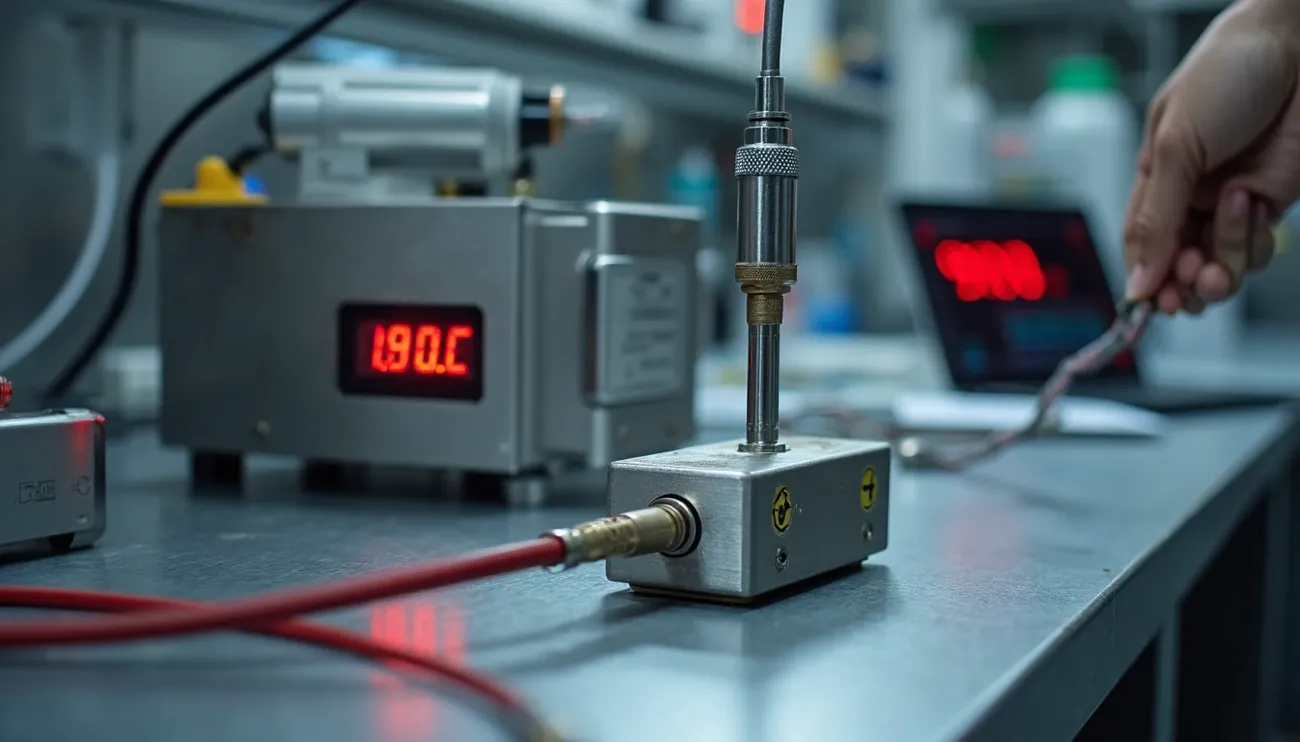
Professionals must use specialized tools to apply flow rate and pressure relationship principles accurately in ground conditions. These instruments let them monitor, troubleshoot, and optimize fluid systems throughout many industries.
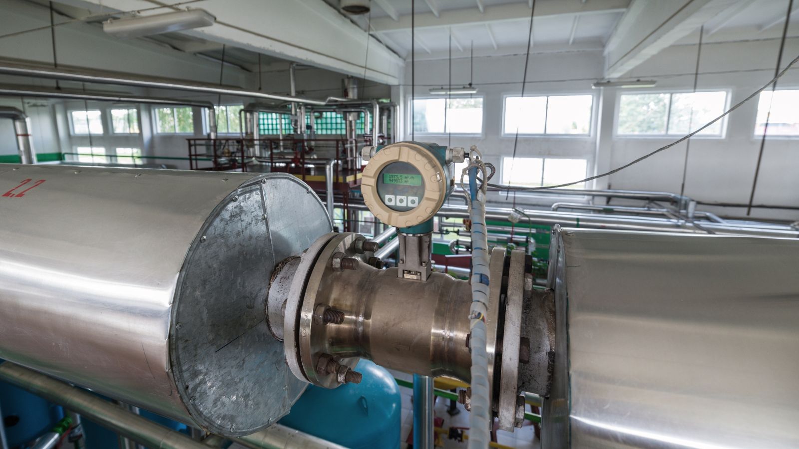
Flow meters and pressure sensors
Flow measurement devices exist in many forms to suit specific applications. Differential pressure flowmeters measure flow using Bernoulli’s principle by creating and measuring pressure differences. You’ll find these popular types:
Orifice plate flowmeters that constrict flow and measure pressure differential before and after
Venturi tube flowmeters that reduce cross-sectional area and generate measurable pressure differences
Averaging pitot tubes that measure impact pressure across pipe diameters
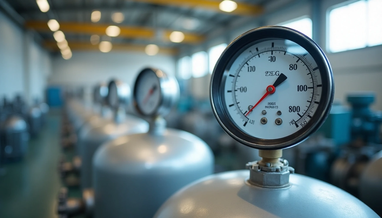
Pressure sensors detect problems early while monitoring system conditions. Industrial pressure sensors play a vital role in equipment condition monitoring. They help improve cost efficiency through predictive maintenance. These sensors measure absolute, gauge, and differential pressure based on what the application needs.
Online calculators and when to trust them
Engineers use many online tools to calculate flow rates from pressure measurements. FluidFlow, to cite an instance, solves continuity of mass, energy, and momentum equations. It shows results for flow rate, pressure loss, velocity, and other parameters. Here are other reliable calculators:
Fluidat from Bronkhorst for calculating flow rates and conversion factors
GIGAcalculator for pipe flow calculations using pressure differences
Engineering Toolbox and Cole-Parmer calculators
In spite of that, these calculators provide estimates that might miss some variables. Pipe roughness, temperature changes, and turbulence can affect actual measurements. Verification against known systems becomes crucial for critical applications.
Industries that just need accurate flow-pressure data
Flow-pressure measurements play a vital role in many sectors. Oil and gas companies use flow measurement to optimize pipeline pressure for efficient transport. Water supply systems use these measurements to design pumps and pipelines with proper pressure levels.
Flow meters make up about 20-25% of all process automation detection instruments’ output value. You’ll find them used in:
HVAC systems to maintain optimal air and water flow rates
Food and pharmaceutical manufacturing that needs precise liquid measurements
Wastewater treatment facilities using electromagnetic flowmeters
Chemical production to monitor corrosive and abrasive fluids
Each application requires specific meter types based on fluid properties, pipe size, and accuracy requirements.
Conclusion
Understanding the Flow Rate-Pressure Connection
Flow rate and pressure relationship formulas might look intimidating at first, yet they control many systems we use every day. This piece explores how these two simple properties interact within fluid systems. Water pressure drops when multiple showers run at once due to the direct relationship between pressure difference and flow rate. Bernoulli’s principle helps us understand why fast-moving fluids put less pressure on pipe walls.
Pipe diameter has a dramatic effect on flow capacity. The flow rate stays proportional to the fourth power of the radius. Small constrictions lead to major flow reductions in piping systems of all sizes. Engineers can design better systems in many applications thanks to the mathematical foundations of Bernoulli’s equation, Poiseuille’s law, and the simple flow rate formula.
These relationships become clearer through practical calculations that help professionals convert pressure readings into flow rates and back. This knowledge matters to design household plumbing and optimize industrial processes. Precise monitoring in ground applications happens through specialized tools like differential pressure flowmeters, venturi tubes, and various pressure sensors.
Without doubt, becoming skilled at these principles creates advantages in industries of all types. System efficiency, safety, and reliability depend on accurate flow-pressure measurements in water networks and chemical plants. The math might look complex, but the physics follows patterns that become user-friendly with practice.