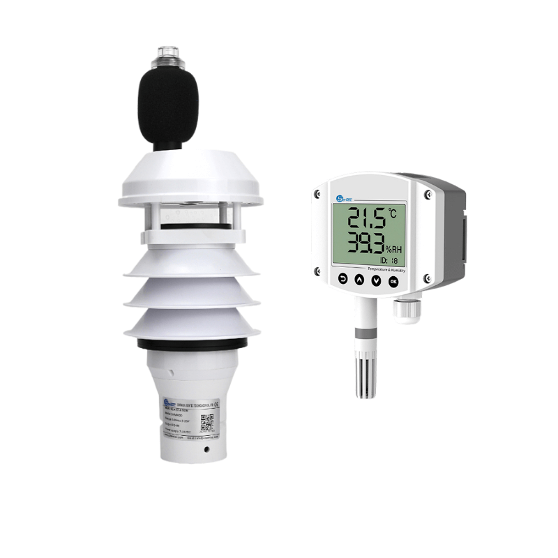
To connect a LoRa wireless transmitter and receiver (RTU gateway) to a computer, you will need to do as follows.
Today we will demonstrate how to connect Lora Pressure transmitter RTU gateway to the computer. We take our PM450 Lora pressure transmitter as example.
Check the packing accessories
When you gets our RTU gateway, you need make every parts clear before connection. First of all, you will have the main body of RTU gateway, an serial cable from USB to RS232 and an antenna (or more), a power adapter from 220VAC to 24VDC
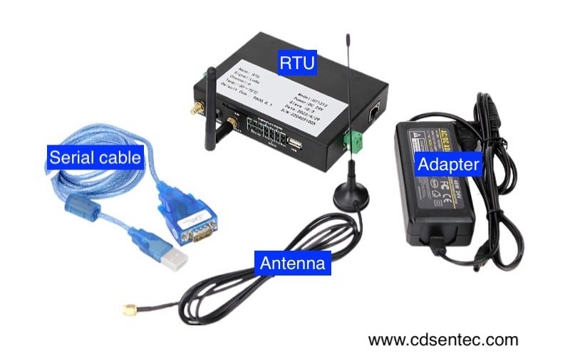
How to connect the wireless transmitter and receiver
If all there parts are ready. You can connect them together now. First connect the supply 24VDC power to the RTU power terminal. You can directly use the power adapter to connect as well. In this demo, we directly use 24VDC constant voltage power supply.
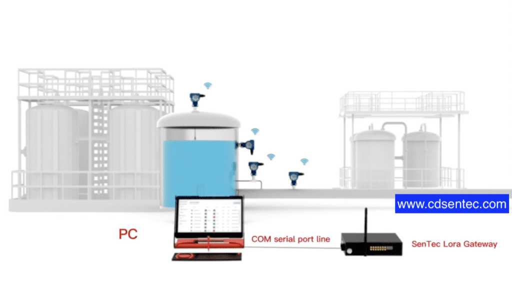
After power on, you can see that the RTU running indicator is on. Above is the power indicator, below one is the running indicator. Then connect the antenna to the zigbee port. After the antenna connection is completed, you need to wait for the sensor to communicate with the RTU. If the communication is connected, a signal indicator will appear on the sensor. This time may wait a little longer.
⚠️RTU supports RS232 interface, RS485 interface, USB interface and Ethernet interface. In the demo video, we mainly demonstrate how to use the RS232 interface to connect with the computer.
In this demo, we use this cable from RS232 interface to USB interface. Please connect the RS232 port to the RTU and connect the USB port to the computer USB port. RTU communication protocol is Modbus RTU standard protocol.
Once the sensor has the signal connection indicator, which indicates that the sensor has been successfully connected with the RTU.
Settings for value reading by Modbus poll
Next, we look at how the computer reads the data in the RTU. We can use the serial port assistant to read the data, or use software that specifically reads RS485, such as Modbus poll. If you have ability, you can also develop some host computer to read data. In this demo, we will use Modbus poll to read RTU data.
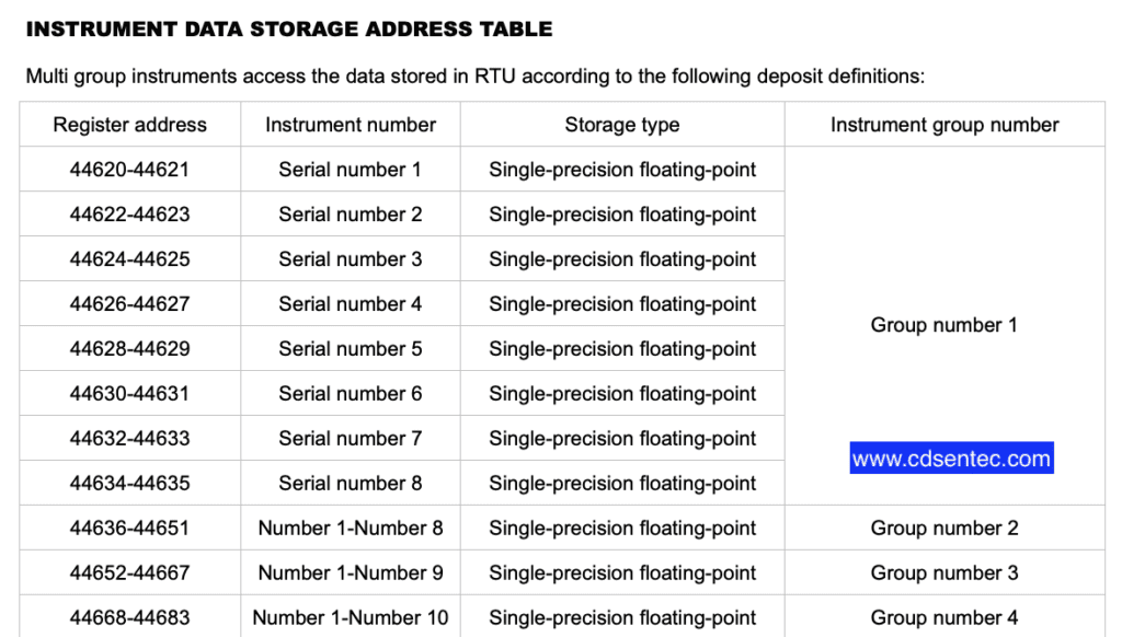
⚠️We also send an RTU operation manual about how to read the RTU data register. On the page, you will find the address of the instrument data register and the parameter about the product pressure and temperature.
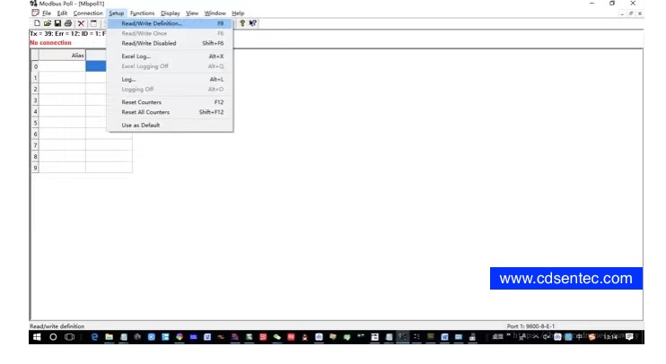
First, on the software interface, there is a setting about reading and writing settings. The setting address of RTU is 1, and this value default does not need to be modified. Function code is 03, read and save the register. The address in the manual is 44620-44621, sensor number 1, single precision floating point number. This is one of the data, we only need to enter this address. The register address is the address of siemens PLC. If you used a register to read, you only need to modify the previous 4-0, and the address will be reduced by 1. For example, this starting address is modified from 44620 to 4919. Because it is a floating point number, 2 numbers are read consecutively, so fill in the number 2 here and click ok. After click connect, please select the serial port number corresponding to the connection. Here we are now connected to port 3, so select 3. Then select 115200 baud rate, 8 data bits, no parity, 1 stop bit, click ok. Now, we can see that the computer reads two 0 values. We can read this more value in the settings by choosing to read 4 bits. Because our tested sensor is a combination of temperature and pressure, there are 2 data stored in it, one is pressure, the other is for temperature. We choose to read 4 consecutively. Because it is a single-precision floating-point number, we can modify this value to a single-precision floating-point number. We can take a look at the meter head to show that the temperature is 24.08 degree Celsius, and the computer also read 24.08 degrees Celsius. This is how the data was read by Modbus pull.
Data reading by software
We offer a free version data reading software. Of course, If you have the ability to develop software, you can also develop the host computer software, which has similar interface with our demo one.
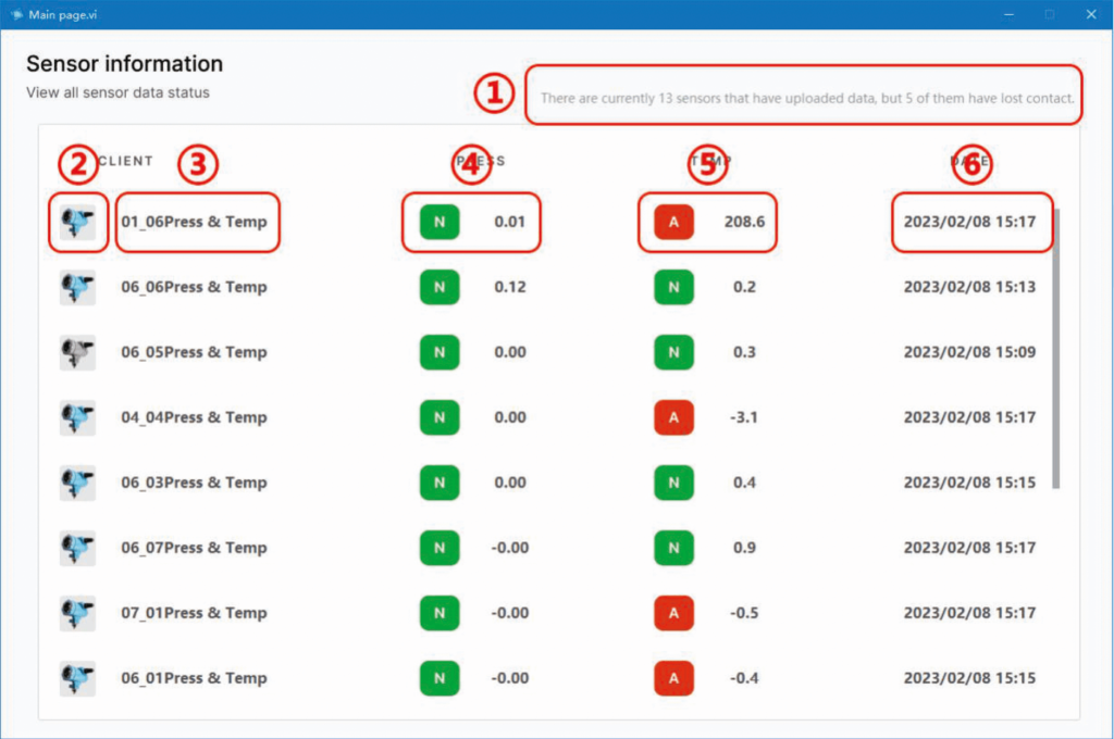
Software operation interface function introduction:
“1”:Number of devices communicating and online.
“2”:Device online status, when the upload interval is longer than the specified time, the icon will show gray.
“3”:Device number and type.
“4”:Sensor Pressure output value.
“5”:Sensor temperature output value.
“6”:Date of last data upload.
We choose the port, the baud rate is unchanged, and then open the communication. Now you can see pressure value corresponding to this products measured. Because this interface can only display the pressure value, so now only the current pressure value is displayed.
Our company also provide host computer software development, but it required additional cost. Please contact our engineer if you need this service
Now we have completed the demonstration of wireless product connection and data reading. If you still have any question during connection, please contact our engineer.

