Tuning fork resonance densitometers offer precise, real-time measurement of fluid density and concentration across a wide range of industrial applications. To ensure accurate and stable readings, correct installation is essential. This guide outlines best practices for installing the densitometer in horizontal and vertical pipes, managing high flow rates, selecting proper pipe sizes, and considerations for open tank installations.
1. Horizontal Pipe Installation
When installing the densitometer on horizontal pipelines, observe the following:
Recommended Installation Position
- Mount on the side of the pipe—not the top—to prevent air entrapment in the tuning fork.
- The gap between the tuning fork tines should be oriented vertically, allowing solids to settle and gases to escape without interfering with measurement.
T-Type Side Insertion Options
Standard Insertion
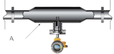
- The tuning fork enters directly into the fluid in the main pipe.
- Suitable for low-viscosity liquids with steady flow.
- Recommended for pipe diameters ≥ 100 mm (4″).
- Fork area flow velocity: ≤1 m/s.
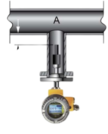
Recessed Insertion
- The fork is recessed 25 mm away from the main stream.
- Avoids strong flow impacts and improves accuracy in unstable or high-speed flows.
- Suitable for pipe diameters ≥ 50 mm (2″).
- Fork area viscosity limit: up to 100 cP (can reach 250 cP in specific cases).
2. Vertical Pipe Installation
For vertical pipelines, the following applies:
Installation Orientation
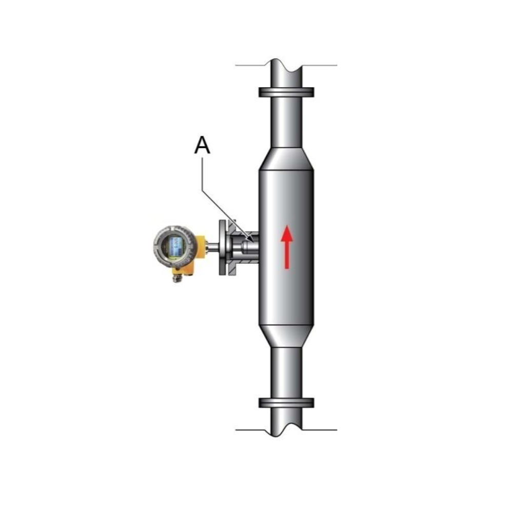
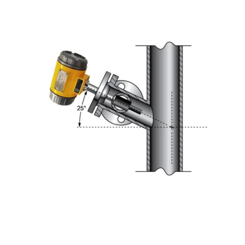
- Install on the side wall, not directly in the main vertical flow stream.
- Preferred flow direction: upward, ensuring full immersion of the tuning fork.
Minimum Pipe Diameter
- At least 150 mm (6″) for standard vertical installation.
- This allows sufficient clearance around the fork for undisturbed vibrations.
3. Pipe Diameter Requirements
- Horizontal installation: pipe diameter must be ≥100 mm (4″).
- Vertical installation: pipe diameter must be ≥150 mm (6″).
- For smaller diameters, accurate measurement is not guaranteed due to wall interference with fork vibration.
4. Managing High Flow Rates
Flow Velocity Limitations
- Ideal fork flow velocity: ≤1 m/s.
- Absolute maximum fluid flow rate through the main pipe: ≤5 m/s (only with appropriate flow conditioning).
Installation Solutions for High Flow
If your system exceeds 1 m/s, implement the following:
Use of Enlarged Pipe Sections
- For each 1 m/s above the limit, increase the pipe diameter by 1.5× at the installation point.
- Helps reduce local flow speed around the sensor.
Required Straight Pipe Lengths
- ≥600 mm upstream, ≥300 mm downstream of the sensor.
- Ensures a stable, laminar flow for accurate measurement.
Reducer Installation
- Use concentric reducers for vertical pipe expansion.
- Use eccentric reducers (flat side down) for horizontal pipe expansion to avoid gas pocket formation.
5. Open Tank Installation Precautions
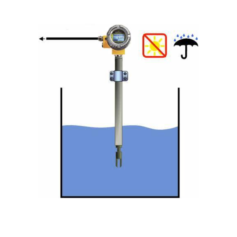
When installing the densitometer in open tanks, several important factors must be considered:
Installation Positioning
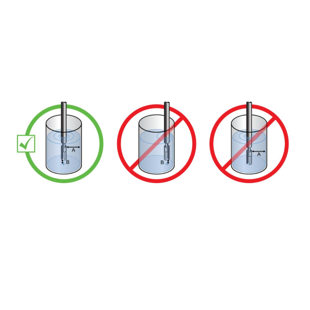
- Avoid placing the sensor near tank walls or agitators.
- Keep at least 200 mm distance from the tank wall and 50 mm from the bottom (in open tanks).
- For closed tanks, ≥50 mm from the wall and ≥200 mm from the bottom.
Avoiding Disturbances
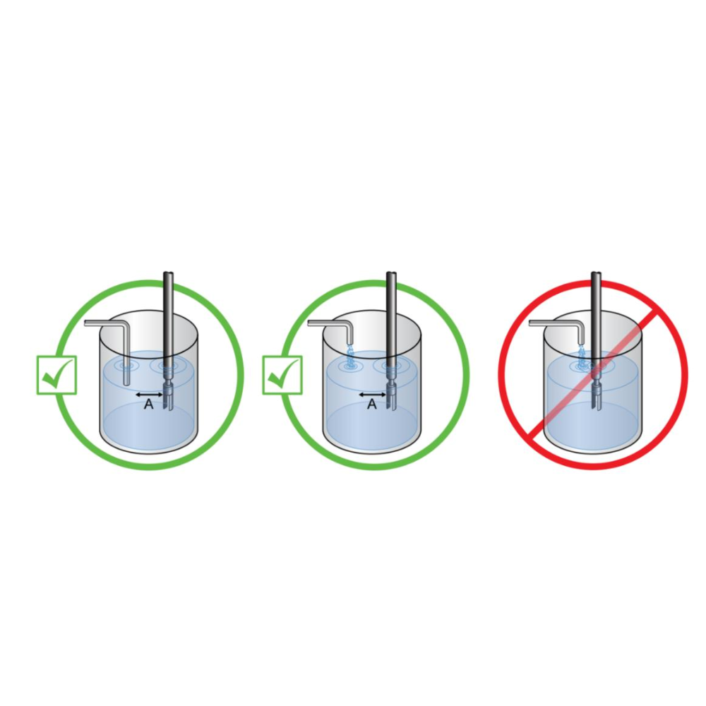
- Install in calm zones away from flow turbulence, mixing blades, or vortex zones.
- Position the tuning fork so that fluid flows through the gap between the tines, not across it.
Submersion Requirement
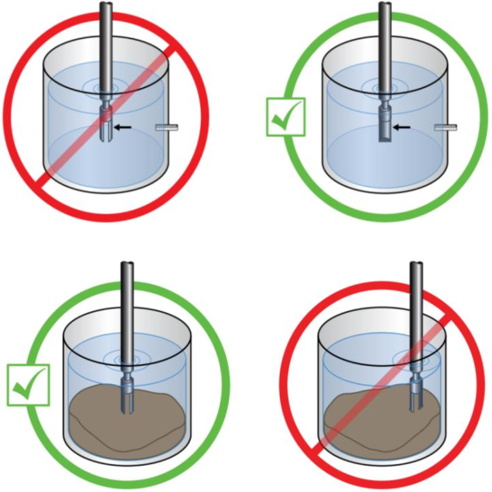
- The fork must remain completely submerged during operation for accurate and stable readings.
Fork Orientation
- Always maintain the tuning fork’s gap in a vertical orientation, regardless of tank or pipe position.
- This avoids measurement errors due to air bubbles or sediment accumulation.
6. Additional Installation Tips
- Distance from Pumps: Always install the sensor at least 5 meters away from any pump to reduce turbulence.
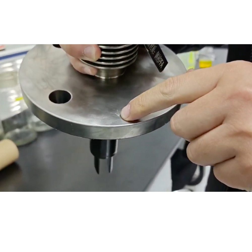
- Mark Alignment: Align the fork with the flow direction using the marking on the sensor housing (dot on hex nut for threaded, lines on flange for flanged).
- Not Suitable For:
- Highly unstable flow conditions
- Pipe diameters <44 mm
- Flocculent or highly viscous fluids (without proper installation method)
Support and Customization
Sentec supports OEM services. If your application has specific requirements—unusual tank shapes, high-viscosity materials, or extreme process conditions—customized sensors and fittings can be provided upon request.
Contact our technical support team for detailed product brochures, sizing calculators, or to request a quote.

