The loop check pressure transmitter refer to the entire “control loop” from primary element (sensor) through the pressure indicator transmitter, and controller, to the valve positioner, and the final control element (valve). Simply, loop is a signal path.
what is Loop Check?
The term “loop” can also refer to a “current loop” which is the pressure transmitter 4 20 mA circuit in series from the current generator through the loads and back.
“Loop check” (“loop test ”) refers to checking of a pressure transmitter 4-20 mA loop to ensure it functions correctly. Direct mount pressure transmitter Loop checking is the process to confirm the signal continuity from primary instrument (pressure transmitters, switches) to DCS or PLC system and from DCS or PLC to the final control elements such as control valves, dampers ON/OFF valves, motor operated valves etc. Loop check is the most common way for the pressure transmitter troubleshooting.
Analog loop check pressure transmitter
A electronic pressure transmitter analog output loop contains the pressure transmitter, power supply, and the receiving device which could be a PLC or DCS.
Pressure Transmitter
A smart pressure transmitter is the device used to transmit data from a sensor over the current loop. There can be only one pressure sensor Transmitter output in any current loop. Here, the pressure transmitter can be replaced by any types of transmitter which converts the real world signal, such as flow, level, temperature, pressure, etc., into the control signal necessary to regulate the flow of current in the current loop. The level of loop current is adjusted by the transmitter to be proportional to the actual sensor input signal.
Power Supply
The analog current loop is supplied power by a DC power supply. The power supply must be set to a level that is greater than the sum of the minimum voltage required to operate the loop powered pressure transmitter, plus the IR drop in the Receiver, and for long transmission distances, the IR drop in the wire. Calculating this drop must consider the maximum level of current that can flow in the 4-20mA current loop for example and not 20mA, but the over-scale or alarm limit of the transmitter.
Just like any other instrument, the impulse line for pressure transmitter power supply operated need to pay attention to different wiring lines.
4-wire and 2-wire pressure transmitters
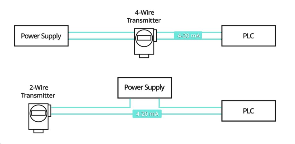
A 4-wire pressure transmitter has 2 wires connected to a power supply and 2 signal wires connected to the PLC. The power supply can be AC or DC depending on the vendor and model.
A 2-wire pressure transmitter circuit has only 2 wires. These 2 wires provide power for the transmitter and are also the signal lines.

Pressure Transmitter Voltage Requirements
The scalable pressure transmitter typically uses 4mA output to represent the calibrated zero input or 0%, and 20mA output to represent a calibrated full-scale input signal or 100%. Because the lowest level of the transmission signal is 4mA or less, the transmitter must be able to operate from less than 4mA. Consequently a two-wire transmitter will have minimum and maximum output voltage ratings that must be observed. The lower voltage is the minimum voltage required to operate the united electric pressure transmitter, and the maximum transmitter voltage is the highest voltage it can withstand.
Receiver
This is the device that receives the transmitted signal. In a pressure transmitter 4 20ma connection process loop, the Receiver could be located thousands of feet from the transmitter. Because it is much easier to measure voltage than current, we often use a resistor to represent the Receiver in a 2-wire current loop. This resistor can be a physical resistor, or simply the input impedance of the receiver channel. The receiver could be any number of different devices, such as: a panel meter, actuator valve, motor speed control, a PLC (Programmable Logic Controller), or other DCS (Digital Control System)
procedure of look check pressure transmitter
Steps in a loop check for a 4-20 mA/HART transmitter may include:
- Check the pressure transmitter, include tag No. and range should correspond with the design datasheet.
- Instruct operations to put the associated control loop in manual according to the pressure transmitter drawing so control is not upset when PV changes when a new value is forced
- Instruct technician to select a test point (4mA,8mA,12mA & 20mA or applied 0 to 100% Physical Input)
- Instruct the technician to tell the person at the control system to note down the system reading for this test point
- Repeat the above two steps for different test points (4mA,8mA,12mA & 20mA or applied 0 to 100% Physical Input)
- Instruct the technician to return the device to normal operation if loop check is completed
- Instruct operations the associated control loop can be put back in automatic
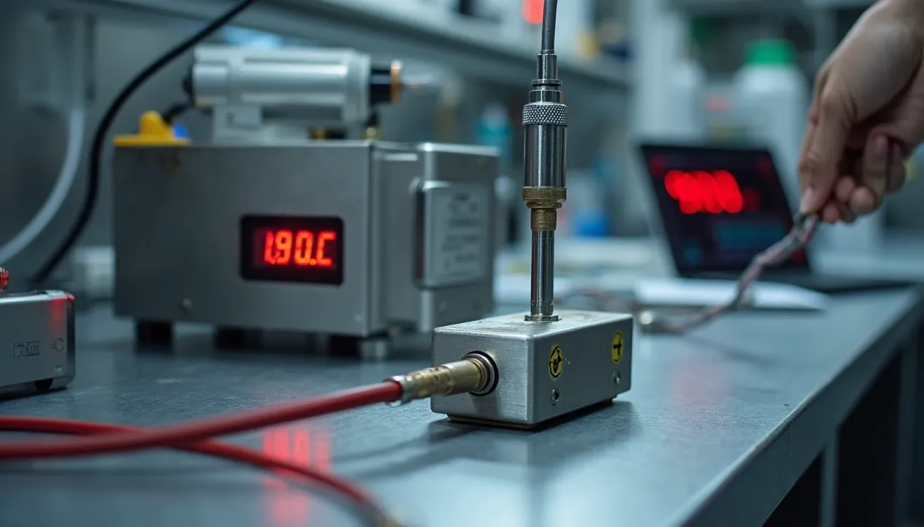
Connection picture of loop check pressure transmitter
procedure of loop check differential pressure/flow transmitter
- Close the HP & LP isolation valves i the k way manifolds and then open the Hp & LP side drain valves.
- Then check the zero is DCS/PLC in control room if zero is ok connect the pressure calibrator on the Hp side of the transmitter then open the LP side to atmosphere.
- Start applying 25%, 50%, 75% & 100% and record the values in DCS/PLC accordingly.
But all the DP flow transmitter are giving out put in square root value. The extraction can be done in DCS so to check the reading of FT in 25% 50% or 75% simulation of differential pressure to be done in square root value.
Digital Loop Check pressure transmitter
The major difference between 4-20 mA/HART and Fieldbus is that 4-20 mA/HART requires five point loop check, but Fieldbus, PROFIBUS, and WirelessHART do not.
For Fieldbus, PROFIBUS, and WirelessHART no 5-point loop check is required because distortion of a digital signal is detected thanks to the error checking which is part of digital communication.
The digital signal is rejected if it has been distorted. This is known as an “overt failure” meaning the error is detected and annunciated. As a result, if the signal is received, it is received correctly, if not, somebody is notified.
So if a pressure transmitter using only digital communication measures 50PSI, the exact same number is received in the control system end. This is why a loop check is not required for digital communication.
Therefore physical input need not be injected, a simple plausibility check based on the prevailing condition is made; such as ambient temperature, atmospheric pressure, empty tank, or no flow etc. Check the measurement status to confirm that it is ‘Good’ meaning the sensor is healthy.


