The pitot tube flow meter has remained a trusted measurement tool since Henri Pitot first used a bent glass tube to measure river velocities in France during the 1700s. Engineers continue to rely on this device because it offers a simple design with no moving parts and measures fluid flow velocity by comparing static pressure and dynamic pressure. This straightforward approach makes it invaluable in industries of all types, from aviation to industrial process control, where accurate flow measurement is critical to optimize efficiency and ensure safety.
This piece will explore the pitot tube working principle and get into the pitot tube formula and calculations derived from Bernoulli’s equation. We’ll compare different types including the averaging pitot tube and explain why this centuries-old technology remains the life-blood of modern fluid velocity measurement.
What is a Pitot Tube Flow Meter and How Does It Work
Simple components and structure
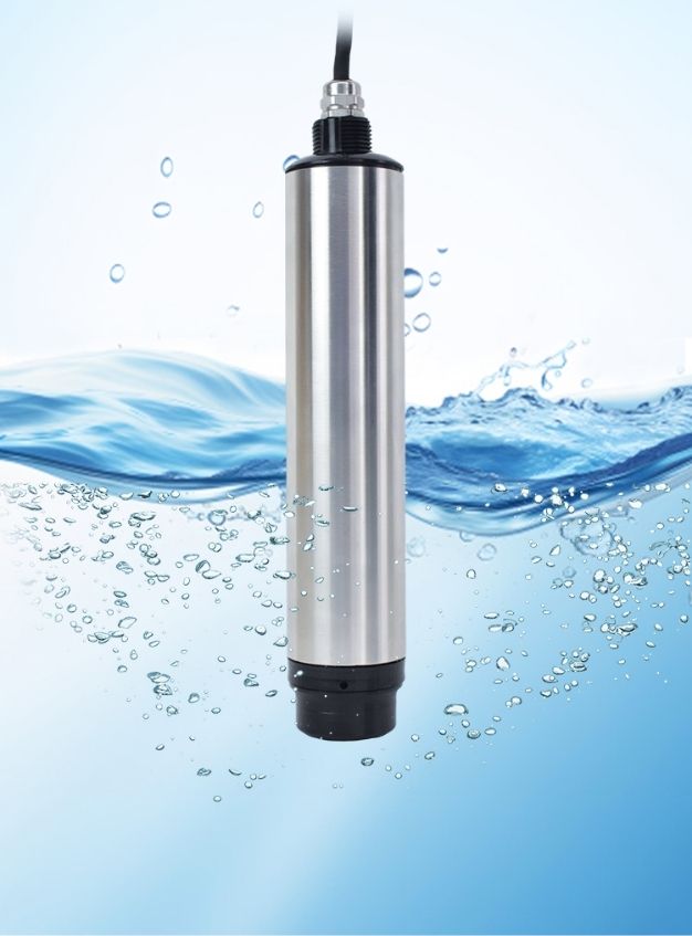
A pitot tube flow meter consists of a dual-tube design within a single probe. The inner tube features an open end facing into the fluid flow and captures total pressure, while the outer tube has small radial holes positioned perpendicular to the flow direction for measuring static pressure. Classical designs use an L-shaped configuration with the open end facing upstream and one or more holes in the outer tube wall behind the open end. The annular space between inner and outer tubes transmits these pressures to separate connections at the opposite end of the probe.
The complete system has several core components beyond just the probe. A differential pressure transmitter converts the pressure difference into an electrical signal, while a flow conversion device transforms this differential pressure signal into flow data for display or transmission. Material selection depends on application requirements. Stainless steel grades like 304 or 316L work for corrosive environments, while brass handles high-temperature conditions.
Pitot tube working principle

The pitot tube working principle centers on converting kinetic energy into potential energy. Fluid flowing through a conduit carries kinetic energy based on its velocity. As fluid enters the pitot tube through the front hole, it has nowhere to escape since the inner tube connects to a pressure transmitter at the back. Once the tube fills, the fluid reaches stagnation inside.
Molecules in the flowing fluid continue building kinetic energy outside the tube. Since fluid can no longer enter the filled inner tube, molecules collide at the front hole and come to a complete stop. Energy conservation dictates this kinetic energy converts into pressure energy with each collision. This pressure buildup at the tip creates what we call stagnation pressure.
Understanding static pressure vs dynamic pressure
Static pressure represents the pressure at rest within the fluid and distributes in all directions. Holes perpendicular to flow direction measure static pressure, which remains unaffected by fluid motion. Dynamic pressure results from fluid movement and acts only in the flow direction.
The relationship between these pressures follows a straightforward pattern: stagnation pressure equals static pressure plus dynamic pressure. The differential pressure transmitter measures this difference and provides the dynamic pressure value needed for velocity calculations.
Pitot tube formula and calculations
The velocity calculation derives from the measured pressure difference and fluid density. The formula reads: v = √(2ΔP/ρ), where v represents flow velocity, ΔP equals the pressure difference between stagnation and static pressure, and ρ denotes fluid density. This square root relationship between velocity and pressure drop limits measurement accuracy to a relatively small turndown range.
Multiply velocity by the conduit’s cross-sectional area to get volumetric flow rate: Qv = (π/4)D²√(2ΔP/ρ), where D represents pipe diameter. Mass flow rate adds another multiplication by fluid density.
The role of Bernoulli’s equation
Bernoulli’s equation provides the theoretical foundation for all pitot tube calculations. The equation states that along a streamline, static pressure plus one half the density times velocity squared equals total pressure. Horizontal flow simplifies this to: p + ½ρv² = constant.
The stagnation point where velocity reaches zero reduces the equation further and allows us to isolate velocity and derive the standard pitot tube formula. This principle assumes incompressible flow, which applies to liquids under nearly all conditions and gasses under certain circumstances.
Types of Pitot Tube Flow Meters
Standard L-type pitot tube
Standard L-type configurations feature an ellipsoidal head with a single forward-facing hole sensing total pressure and a ring of side holes capturing static pressure. Stainless steel construction allows these tubes to operate at temperatures up to 680°C continuously and 800°C intermittently for larger diameters. L-type designs suit clean gas environments but become susceptible to blockage when measuring high-dust flue gas.
S-type pitot tube for dusty applications
Engineers designed the S-type pitot tube for industrial stacks operating in high-dust environments. This design incorporates large pressure orifices and robust tube construction compared to L-type variants. Two similarly shaped hollow metal tubes welded together form the S-configuration. South Korea’s Continuous Emission Monitoring System relies on S-type tubes for greenhouse gas measurements from industrial smokestacks. S-type specifications lack standardization across manufacturers, unlike L-type geometry. This creates variations in measurement accuracy.
Averaging pitot tube for accurate measurements
Averaging pitot tubes overcome single-point measurement limitations. They use multiple impact and static pressure ports that extend across the whole pipe diameter. Pressures from all impact ports combine separately from static ports, and their differential indicates average flow. This multiport design especially benefits applications where flow profiles remain undeveloped.
2D and 3D pitot tubes for complex flows
Multi-holed pitot tubes measure velocity, yaw and pitch angles when precise flow alignment proves difficult. The EPA approves these instruments for regulatory greenhouse gas flux measurements from smokestacks. Calibration complexity requires thousands of measured points distributed as tables rather than simple coefficients.
Why Engineers Choose Pitot Tube Flow Meters
Simple design with no moving parts
Engineers appreciate pitot tube flow meters because they contain zero moving parts. This eliminates mechanical wear and maintains long-term accuracy. The absence of moving components means no sharp edges deteriorate over time, which translates to reliable measurements across extended operational periods.
Low installation and maintenance costs
Installation costs remain minimal since the slender probe fits through a 5/16-inch diameter hole in ducts. Hot tapping capability allows insertion into existing pressurized pipelines without shutdowns. Maintenance requirements stay low given the strong construction and lack of mechanical components. Occasional gas purging through pressure ports clears sensing ports when dirt appears.
Minimal pressure drop in the system
Pitot tubes cause very little pressure loss in flowing streams[132]. Averaging pitot tubes generate permanent pressure loss at only 3% of differential pressure measurement and reduce energy costs significantly.
Reliable performance in harsh conditions
These instruments function in a variety of environments, including high-pressure and high-temperature conditions. Standard models handle temperatures up to 200°F, while specialized versions operate at 400°F and pressures reaching 1500 psig.
Wide range of industrial applications
Pitot tubes accommodate pipe diameters up to 72 inches and larger[132]. They work well in square, rectangular, or circular ducts[132].
Budget-friendly manufacturing and global availability
Pitot tubes cost less than orifice plates while delivering comparable 0.5% to 5% accuracy. Chinese manufacturers benefit from direct access to competitively priced stainless steel from domestic producers and mature precision machining industries that enable faster delivery and flexible customization at superior cost-performance ratios.
Applications and Selection Guide
Aviation and aerospace measurements
Aircraft rely on pitot tubes as speedometers, with the actual tube measuring around 10 inches long and 1/2 inch in diameter. Several small holes drilled around the outside connect to one side of a pressure transducer, while the center hole drilled down the axis connects to the other side. The transducer measures strain in a thin element using an electronic strain gage to determine velocity. The center tube points toward travel direction, with mounting on the nose or wing.
HVAC and duct airflow monitoring
HVAC systems use pitot tubes for duct airflow monitoring to ensure balanced air distribution and detect inefficiencies. These applications suit mid to high velocity measurements, with recommended airflow ranging from 200 FPM minimum to 3000 FPM maximum. Typical HVAC environments see operating temperatures span 40 to 120°F.
Steam and gas flow in industrial processes
Power plants and industrial facilities measure steam flow using pitot tubes to monitor boiler output. Area-averaging pitot stations handle large flows of low pressure air in boilers, dryers and HVAC systems. Permanently installed units operate at pressures up to 1400 PSIG through flanged or screw connections[233].
Selecting the right pitot tube for your application
Selection begins with understanding fluid type, as gas versus liquid properties affect material choice and design. Flow range expectations help match the pitot tube to specific velocities. Temperature and pressure conditions determine whether standard or specialized models work best. We benefit from China’s manufacturing ecosystem, with access to stainless steel from domestic producers and mature precision machining industries that enable faster delivery and flexible customization at superior cost-performance ratios.
Installation best practices
Position the pitot tube at least 10 pipe diameters downstream from bends. Provide 5 to 10 pipe diameters of straight run before the installation point for stable readings. The stagnation port must face into the flow when you orient the tube. Think about environmental conditions including vibration, temperature variations and corrosive substance exposure. Turbulent air streams prevent accurate readings, so insert at least 8-1/2 duct diameters downstream from elbows or obstructions.
Conclusion
The pitot tube remains an engineering staple because it delivers accurate flow measurements through a simple design. This technology has no moving parts, creates minimal pressure drop, and adapts to countless applications. It continues proving its worth centuries after its invention. Selecting a pitot tube for your application requires careful matching of the design type to your specific conditions, especially fluid properties, flow range and environmental factors. We utilize China’s manufacturing advantages to provide reliable instruments at competitive prices. You get proven measurement technology without compromising your budget.