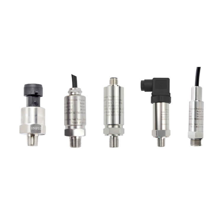
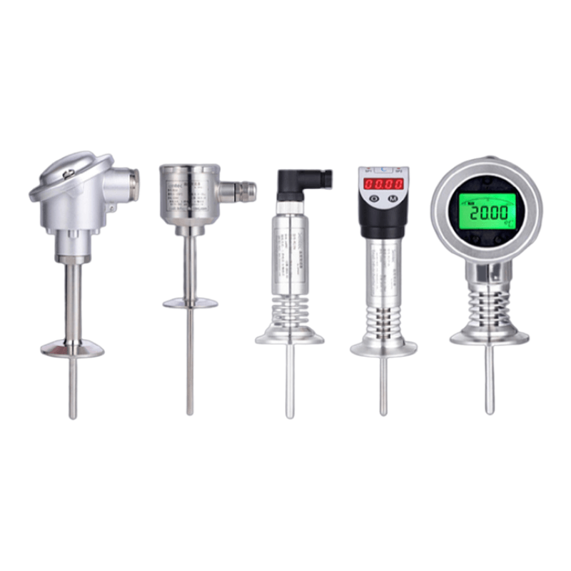
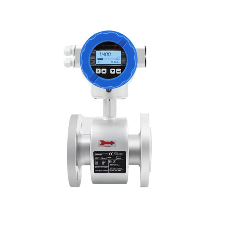
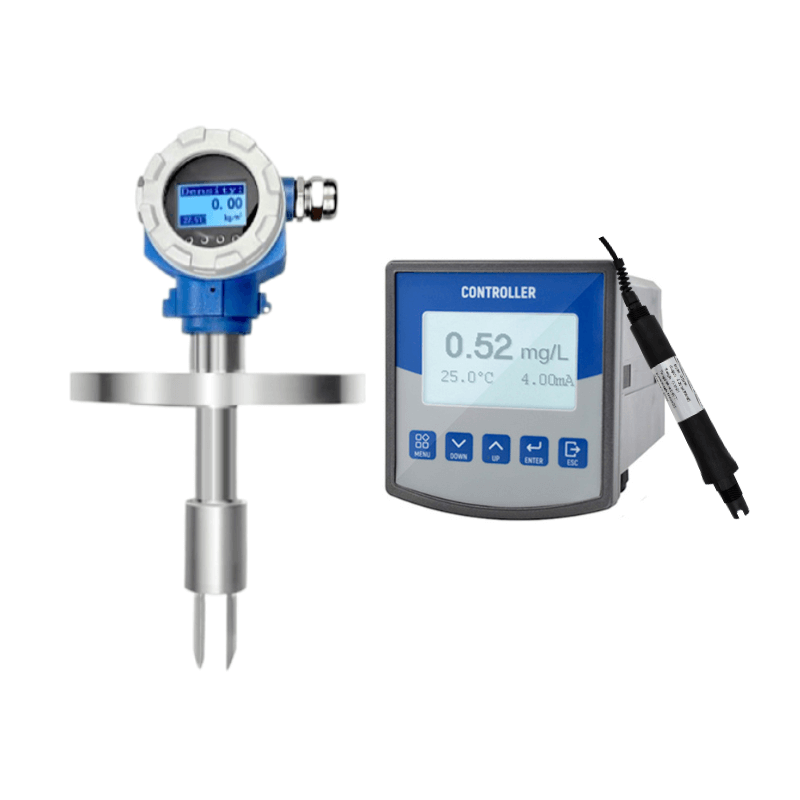
A pressure transducer 4 20ma is a device used to measure and convert pressure into an electrical signal. The 4-20mA standard is a common method of transmitting sensor data in industrial applications. In a 4-20mA pressure transducer, the output current is directly proportional to the measured pressure. A pressure range is assigned to the 4-20mA signal, where 4mA corresponds to the minimum pressure and 20mA corresponds to the maximum pressure. This standardized signal allows for easy integration with other industrial devices and ensures accurate and reliable pressure measurement.
In industry, the most widely used is to transmit analog quantity with 4~20mA current. So. The knowledge of 4-20ma pressure transducer test troubleshooting will be important to help you quickly eliminate product faults and use analog transducer products normally in field use.
How does a 4 20ma pressure transducer work ?
A 4-20mA pressure transducer works by converting the measured pressure into a current signal that ranges from 4mA to 20mA. The current signal is directly proportional to the pressure being measured, with 4mA representing the minimum pressure and 20mA representing the maximum pressure.
This standardized current signal allows for easy integration with other industrial devices and ensures accurate and reliable pressure measurement. The transducer typically uses a sensing element, such as a strain gauge or capacitance sensor, to detect the pressure and convert it into an electrical signal. The current output is then adjusted accordingly to reflect the pressure measurement.
How to wire a 4-20ma pressure transducer?
Wiring a 4-20mA pressure transducer involves a few simple steps. Here’s a general guide:
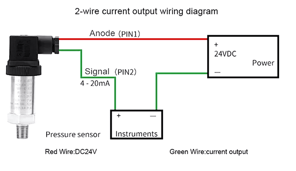
4 20ma pressure transducer wiring diagram
- Power Supply: Connect the positive terminal of the power supply to the positive terminal of the transducer. Connect the negative terminal of the power supply to the negative terminal of the transducer.
- Load Resistor: Connect a load resistor between the positive terminal of the transducer and the positive terminal of the power supply. The value of the load resistor depends on the desired output range and should be calculated using Ohm’s law.
- Signal Output: Connect the positive terminal of the transducer to the positive terminal of the output device (e.g., a PLC or data acquisition system). Connect the negative terminal of the transducer to the negative terminal of the output device.
- Grounding: Ensure proper grounding by connecting the ground terminal of the power supply, the transducer, and the output device together.
Remember to consult the manufacturer’s documentation for specific wiring instructions and to follow any safety guidelines.
How to test a Pressure transducer 4 20ma ?
After you wired the Pressure transducer 4-20ma. You need be ready for test it. Before test, make sure you do as follows:
Please check before testing
1) Check the product nameplate to determine if the system pressure is less than the full range pressure of the transmitter;
2) Is the tested medium compatible with the product;
3) Confirm that the tested medium will not block the inlet hole;
Testing the installation process
1) In general, the transmitter should be installed vertically upwards and horizontally,
As shown in the figure, due to limitations, it is necessary to install horizontally and pay attention to the product
Does the zero point of have an offset;
2) Sealing: The maximum torque depends on the installation point (such as material and shape). If you have any questions, please contact our application engineer;
The sealing type is determined based on the thread specification:

4-20ma pressure transducer troubleshooting
4 Typical faults and solutions for 4-20ma pressure transducer troubleshooting
1.The 4-20ma pressure transducer has no output and no display
| Check and Test | Solutions |
| Check if the power supply is reversed. | Put it in the correct way. |
| Check the power supply of the pressure transducer if it is 24VDC. | Make sure the pressure transducer is power supplied ≥12V(intelligent type)≥15V(general type). If there is no power supply, check if the circuit is open and detect the secondary instrument/PLC sampling resistance (input impedance should be ≤250Ω). |
| If it is a displayable 0-100 psi pressure transducer 4-20ma, check if the indicator is damaged (you can short the two wires of the indicator first. If it is normal after a short circuit, it means the indicator is damaged). | Replace the indicator. |
| Connect the ammeter to the 24V power circuit and check if the current is normal. | If it is normal, the miniature pressure transducer is normal. In this case, check if other instruments in the circuit are normal. |
| Check if the wiring is loose or not. | Make it tightened and well connected. |
| Check if the power supply is correctly connected to the power input terminal. | Connect to the power supply terminal correctly according to the power supply requirements. |
2. Pressure transducer 4 20ma output ≥ 20mA
| Check and Test | Solutions |
| Check if the barometric pressure transducer power supply is normal. | If it is less than 12VDC, check whether there is a large load in the circuit. The load capacity of the pressure transducer should be in accordance with RL ≤(transducer supply voltage -12V)/( 0.02A) Ω. |
| Check whether the actual pressure exceeds full range limits. | Change a pressure transducer with an appropriate range, like 0-100 psi pressure transducer. |
| Check symbol for pressure transducer whether is damaged. Severe overload sometimes damages isolated diaphragm. | Return the pressure transducer to the factory for maintenance. |
| Check whether the power supply wiring is correct. | Put it in an incorrect way. |
3. Water pressure transducer 4 20ma output≤4mA
| Check and Test | Solutions |
| Check if the pressure transducer power supply is normal. | If it is less than 12VDC, check whether there is a large load in the circuit. The load capacity of the pressure transducer should be in accordance with RL≤ (transducer supply voltage -12V) / ( 0.02A) Ω. |
| Check whether the wiring is loose or not which causes the contact resistance to increase. It is equivalent to the load increase. | Connect the wire and tighten it, the load is in accordance with RL≤ (transducer supply voltage-12V) /(0.02A) Ω. |
| Check whether the actual pressure exceeds the selected range of the pressure transducer readout. | Change a pressure transducer with an appropriate range. |
| Check pressure transducer symbol whether it is damaged. Severe overload sometimes damages the isolated diaphragm | Return the pressure transducer to the factory for maintenance |
4. The pressure display/output signal is incorrect and has errors
| Check and Test | Solutions |
| Check if the pressure transducer tester power supply is normal. | If it is less than 12VDC, check whether there is a large load in the circuit. The load capacity of the pressure transducer calibration should be in accordance with RL ≤ (transducer supply voltage -12V)/( 0.02A) Ω. |
| Check if the reference pressure value is correct. | Replace the same type, better same range, like 0-100 pressure transducer, if the error is consistent, check the reference pressure meter. If the meter accuracy is low, you need to change the instrument with higher precision. |
| Check if the range of the secondary meter consistent with the range of an input transducer converts | Adjust the range of the secondary instrument to make sure it is consistent with the range of the pressure transducer. |
| The capacity of the pressure transducer load should be in accordance with RL≤ (transducer supply voltage -12V)/(0.02A) Ω. | If it is not, take measures according to its different conditions: such as raising the power supply voltage (but must be lower than 36VDC), reducing the load, etc. |
| Check if the corresponding device housing is reliably grounded. | If not, make it reliably grounded. |
| Check whether the strong and weak electricity is separately arranged onsite. | Make sure the wiring is scientific and reasonable, avoiding interference for pressure transducer signal instability/error. |
| The pressure transducer diaphragm is easily deformed. Overload and hard objects may damage isolated diaphragm. | Return the pressure transducer to the factory for maintenance. |
| Check the pipeline When the pipeline has impurities, the measurement accuracy will be affected. | Clean the impurities and add a filter screen before the pressure port. |
3 extra failures for Pressure transducer 4 20ma troubleshooting
1. If the input of the pressure indicating instrument is 4~20mA, the output signal of the transducer can be directly connected; if the input of the pressure indicating instrument is 1~5V, it must be connected to the input end of the pressure indicating instrument with an accuracy of 1,000. 1/1 and above, the resistance value is 250Ω, and then connect to the input of the transducer.
2. If the input terminal of the multi-point paper recorder is not recording, if the input terminal is open: 1. No other load can be carried; 2. Use other recorders whose input impedance is less than or equal to 250Ω when there is no recording.
3. If the temperature of the pipeline is too high, add a buffer tube to dissipate heat. It is best to add some cold water to the buffer tube before use to prevent the superheated steam from directly impacting the high temperature pressure transducer, thereby damaging the transducer or reducing its service life.
Additional faults for the 4-20ma pressure transducer troubleshooting
1. Pressure transducer installation problems
In the steam flow measurement, there are mainly two types of steam, one is the externally supplied steam and the other is the superheated steam of the boiler. The externally supplied steam is the steam after desuperheating and decompression. The temperature is not high, and it is mixed with a large amount of water. It is not used when needed, and the steam flow is always changed according to the user’s requirements. In the actual flow measurement process, sometimes the flow rate is too large and sometimes the flow rate is too small, which is very unstable and often needs to be drained. The measurement of the steam pressure transducer is accurate after each blowdown, but the number of blowdowns in the steam pipeline is too many, which is easy to cause Steam leaks from each contact on the pressure guiding pipe.
In the use of measuring superheated steam, the biggest problem is found that sometimes the machine stops, and the pressure transducer airflow will deviate after restarting, resulting in inaccuracy, and sometimes there is still a little flow display after stopping. Generally, the installation position of the current to pressure transducer is lower than the measuring pipe. However, in the actual installation, the condensing tank and the automation direct pressure transducer for the external steam flow are higher than the measuring pipeline, and the pressure guiding pipeline with at least 1 meter down from the throttling device is too short.
The superheated steam flow of the boiler also has the problem of inconsistency in the height of the condensing tank and the measuring pipe, which leads to the unbalanced height of the condensed water and causes the static pressure difference.
2. The pressure guiding tube is blocked
In pressure measurement, sometimes the indicated pressure does not vary with operating conditions. After opening the drain valve, there is only a small amount of sewage and no water will flow out. This is because there will be a small amount of floating dust in the water quality or compressed air, which will enter the pressure guiding pipe to settle with the water flow. Over time, the wall of the pressure guiding pipe will corrode and foul, causing blockage.
3. The fault of the pressure transducer device itself
In the measurement of lubricating oil pressure, the lubricating oil pressure signal participates in shutdown interlock control. The signal measured by the lubricating oil pressure sensors and transducers are transmitted to the computer. On the one hand, it is displayed. On the other hand, the signal is also compared through the program. When the pressure is lower than 0.06MPa, the oil shortage shutdown signal is issued to stop the machine.
From the lubricating oil pressure signal trend chart, it can be seen that the pressure is instantaneously plummeting, which leads to the tripping. After checking the transducer, it is found that the internal module of the transducer is damaged. Although the transducer is regularly calibrated every year, it is used for production after passing the calibration. After several years of operation of the transducer, its performance indicators such as accuracy, sensitivity, and stability will gradually decrease, and the internal diaphragm and integrated block will also be damaged and fail.
4. There are interference problems
In the measurement of the exhaust pressure of the air compressor, the fluctuation of the exhaust pressure signal is large. After verifying, for example, 0-500 psi pressure transducer, it meets the accuracy requirements and eliminates the fault of the transducer itself; check that the pressure guiding pipe and the joint are not damaged or leaked, and the connection of the signal cable is in good contact. However, the direction of the cables is introduced into the control room through the cable tray next to the high distribution room. There is a lot of electromagnetic interference around.
In conclusion
By learning this article content, you may solve some problem by yourself. if you need more help for the 4-20ma pressure transducer troubleshooting, you can ask our engineer to get the transducer catalog.

