Wind speed sensor is a common sensor that can continuously measure wind speed and air volume (air volume = wind speed x cross-sectional area). The wind speed sensor types is roughly divided into mechanical (mainly propeller type, wind cup type) wind speed sensor, hot air type wind speed sensor, pitot tube wind speed sensor and ultrasonic wind speed sensor based on acoustic principle, the shell is made of high quality aluminum alloy profile or polycarbonate Composite material, rain-proof, corrosion-resistant and anti-aging, is a smart instrument that is easy to use, safe and reliable. It is mainly used in meteorology, agriculture, ships and other fields, and can be used outdoors for a long time.

Propeller wind speed sensor
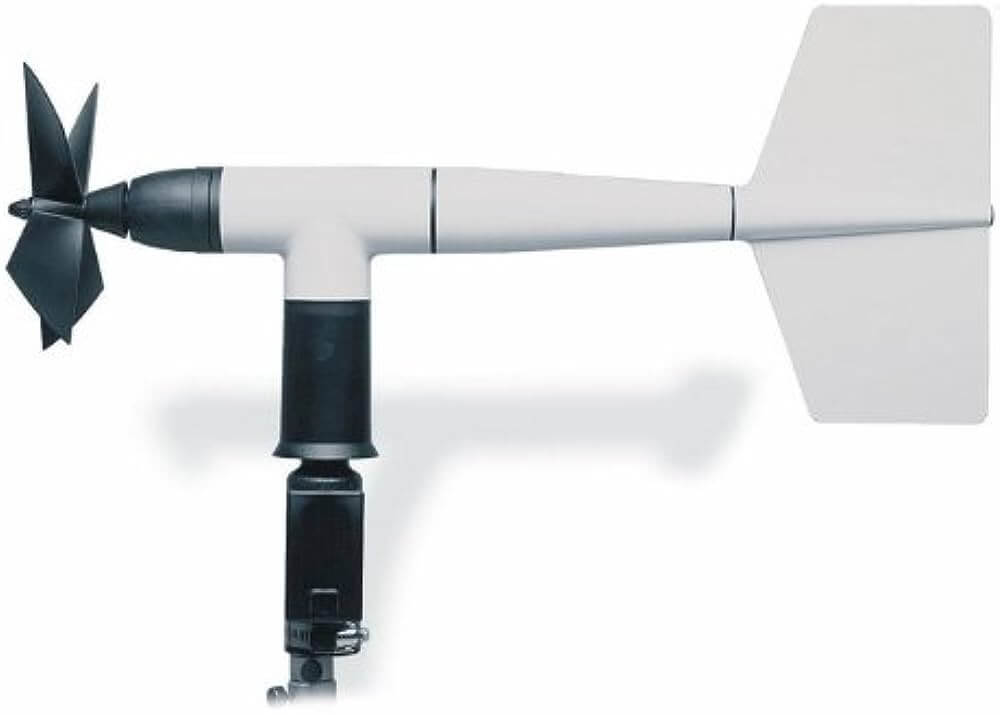
Propeller wind speed sensor is mainly composed of propeller blade, sensor shaft, sensor bracket and magnetic induction coil. It uses the kinetic energy of the flowing air to push the sensor’s propeller to rotate, and then calculates the air flow rate through the terminal device by the speed of the propeller.
The electric fan is driven by the motor to rotate the fan blades, creating a pressure difference between the front and back of the blades, which promotes the air flow. The working principle of the propeller anemometer is just the opposite. The blade system aligned with the air flow is subjected to the wind pressure, and a certain torque is generated to rotate the blade system. Usually the propeller-type speed sensor measures the wind speed by rotating a group of three-blade or four-blade propellers around a horizontal axis. The propeller is generally installed at the front of a wind vane, so that its plane of rotation is always facing the direction of the wind, and its speed is proportional to the wind speed.
Wind cup wind speed sensor
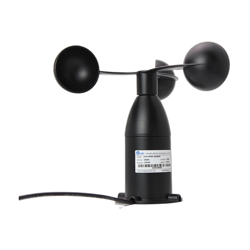
The wind cup type wind speed sensor is a very common wind speed sensor. It was first invented by Rubin Sun. The induction part is composed of three or four conical or hemispherical empty cups. The hollow cup shells are fixed on a three-pointed star-shaped bracket that is 120° to each other or a cross-shaped bracket that is 90° to each other. The concave surfaces of the cups are arranged in one direction, and the entire transverse arm bracket is fixed on a vertical rotation axis.
When the wind blows from the left, the wind cup 1 is parallel to the wind direction, and the component of the pressure of the wind on the wind cup 1 in the direction most perpendicular to the axis of the wind cup is approximately zero. The wind cups 2 and 3 intersect at a 60-degree angle with the same wind direction. For the wind cup 2, its concave surface is facing the wind and the wind pressure is the largest; the wind cup 3 has its convex surface facing the wind, and the wind’s circumfluence makes it subjected to the wind pressure It is smaller than the wind cup 2. Due to the pressure difference between the wind cup 2 and the wind cup 3 in the direction perpendicular to the wind cup axis, the wind cup starts to rotate clockwise. The greater the wind speed, the greater the initial pressure difference. The greater the acceleration, the faster the wind cup rotates.
After the wind cup starts to rotate, because the cup 2 rotates in the direction of the wind, the pressure of the wind is relatively reduced, and the cup 3 rotates at the same speed against the wind, the wind pressure is relatively increased, and the wind pressure difference is continuously reduced. After a period of time (when the wind speed is constant), when the partial pressure difference acting on the three wind cups is zero, the wind cup will change to rotate at a constant speed. In this way, the size of the wind speed can be determined according to the speed of the wind cup (revolutions per second).
When the wind cup rotates, it drives the coaxial multi-tooth truncated disc or magnet bar to rotate, and a pulse signal proportional to the speed of the wind cup is obtained through the circuit. The pulse signal is counted by the counter, and the actual wind speed value can be obtained after conversion. At present, the new rotating cup anemometers use three cups, and the performance of the conical cup is better than the hemispherical. When the wind speed increases, the rotating cup can quickly increase the speed to adapt to the airflow speed. When the wind speed decreases, the speed is reduced due to inertia. However, the wind speed indicated by the rotary anemometer in the gust wind is generally too high and becomes too high effect (the average error generated is about 10%)
Two prohibitions:
1. The use of wind speed sensors in flammable gas environments is prohibited,
2. It is forbidden to put the wind speed sensor probe in flammable gas.
Seven don’t:
1. Do not disassemble or modify the wind speed sensor;
2. Do not expose the probe and the anemometer body to rain;
3. Do not touch the sensor part inside the probe;
4. Do not place the anemometer in a place with high temperature, high humidity, dust and direct sunlight;
5. Do not use volatile liquid to wipe the wind speed sensor;
6. Do not drop or press the wind speed sensor;
7. Do not touch the sensor part of the probe when the anemometer is charged.
The mechanical wind speed sensor needs to pay attention to the following points during the installation process:
The distance between the wind measuring device and the obstacle is at least equal to more than ten times the height of the obstacle itself. If this requirement cannot be met, the device should be placed approximately 6-10 meters above the obstacle.
If the wind measurement equipment needs to be installed on the roof, it should be installed in the center of the flat roof, not side by side, to avoid the tendency of a certain direction.
Because the device needs to be installed in a higher position, the use of the wind speed sensor requires the use of a bracket to complete the measurement of the wind speed. However, this bracket must have good wind resistance and can be disassembled at any time when needed. , In order to ensure that the daily maintenance work can be carried out smoothly.
In the process of using the instrument, if it is used properly, the instrument does not need maintenance, but serious pollution will cause the gap between the rotating part and the stationary part of the instrument, so it is necessary to remove the dirt regularly. Thunderstorm weather usually damages this type of electronic equipment. If lightning protection measures are not taken, there is a possibility of damage to the equipment. Therefore, installing wind speed sensors at a higher position must take lightning protection measures.
Ultrasonic wind speed sensor
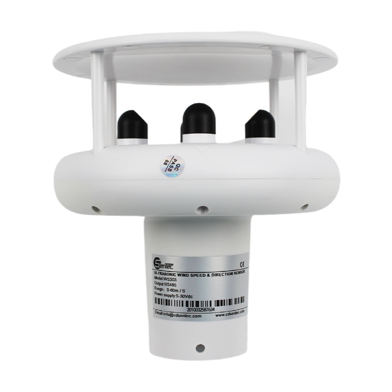
Ultrasonic wind speed sensors mainly use the ultrasonic time difference method to achieve wind speed measurement. The speed of sound propagation in the air will be superimposed on the air velocity in the wind direction. If the propagation direction of the ultrasonic wave is the same as the wind direction, its speed will be accelerated; otherwise, its speed will become slower. Therefore, under a fixed detection condition, the speed of ultrasonic wave propagation in the air can correspond to the wind speed function. The exact wind speed and direction can be obtained through calculation.
Compared with traditional mechanical wind speed and direction sensors, ultrasonic wind speed and direction sensors have the following four advantages:
No inertial measurement, no start wind speed limit, zero wind speed work, 360° all-round no angle limit, can obtain wind speed and wind direction values at the same time;
Adopt integrated structure design, no moving parts as a whole, the shell is made of engineering plastic material, with little wear and long service life;
Using random error identification technology, it can also ensure low discrete error of measurement under strong wind and make the output more stable;
The equipment does not need on-site calibration and maintenance, and the real work is 0~359° (no dead angle).
For more information, Please contact us, our sales engineer will help you choose the most suitable product.

