Radar level measurement technology has become the preferred solution for engineers who work with challenging bypass installations. Radar level transmitters reliably measure tanks that reach 30 to 40 meters in height. Advanced models can even measure up to 150 meters. These impressive capabilities make radar an invaluable tool for chemical plants, oil and gas facilities, and water treatment systems.
Engineers must carefully choose between different radar technologies for bypass installations. Non-contact radar level sensors work well with spherical, horizontal, and cylindrical tanks. Guided wave radar level transmitters prove especially effective with medium fluctuations or foam. These transmitters can measure up to 30 meters accurately and eliminate steam interference that could affect measurement quality. This piece explains why more engineers now prefer radar type level measurement for bypass installations and helps you pick the right radar waveguide that matches your application requirements.
Why bypass installations need special level measurement
Process vessels create tough measurement challenges that standard level instruments can’t handle. Bypass installations are now essential to get accurate level measurements in complex industrial settings.
Challenges in turbulent or narrow vessels
Getting precise level measurements becomes really tough when dealing with turbulence. Mixing applications use agitators that create heavy turbulence and whirlpool effects. These disrupt the liquid surface and make stable readings almost impossible. The churning action makes the surface move up and down fast. This causes traditional level sensors to “chatter” – they cycle on and off quickly, which makes them less accurate and wear out faster.
Foam makes things even trickier. When mechanical agitators run, they often create foam layers that can lead to dangerous overfill situations if you don’t watch them carefully. The chemical processes also run under tough conditions:
Near vacuum or negative pressure environments
Temperatures reaching up to 410°F (210°C)
Very corrosive media that damages standard instruments
Viscosity changes that affect how reliable measurements are
Narrow vessels come with their own set of problems. Reactor tanks usually have lots of internal parts—heating coils, baffles, and multi-level agitators—that mess with sensor signals. Tanks with odd shapes and tall or awkward nozzles make it very hard to install sensors properly.
Why traditional sensors fall short
Traditional level measurement tools don’t work well in these tough conditions. Float switches are simple and cheap, but they have big drawbacks. They break down easily, aren’t very accurate, and fluid temperature and viscosity changes affect them a lot. They also wear out too fast and give wrong readings in turbulent conditions.
Mechanical level devices like displacers break down often and need lots of maintenance. These old-school tools also need to adjust for density changes during chemical reactions. If they don’t, they’ll give wrong readings, which makes them expensive to keep running.
Ultrasonic sensors run into other big issues. Vapor can absorb, scatter, or bounce their signals back, which leads to unreliable measurements. The signals get distorted when there’s agitation, which really hurts accuracy. Even small temperature changes can throw off the readings.
Dye markers and mechanical gages are simple but don’t perform well in tough environments. They’re only accurate within ±1-5% for float and dye markers. Compare that to radar sensors that can be accurate up to ±0.1%.
Traditional sensors really show their limits in vessels that have:
Different agitator designs (paddle blades, ribbon blades, multiple impellers)
Vacuum conditions with corrosive media
Quick temperature and pressure changes
Foam or turbulence near where you’re measuring
These limitations show why we need better solutions. Bypass chambers solve these problems by creating a calm spot to measure that’s separate from the main vessel’s turbulence. They work like stilling wells that make measurements much more reliable.
Benefits of radar level measurement in bypass setups
Engineers now prefer radar technology in bypass applications because of its exceptional performance. Traditional measurement methods can’t match radar’s reliable measurements in tough process conditions.
Stable readings in agitated or foamy conditions
Bypass chambers work like stilling wells. They create calm measurement environments even when the main vessel experiences heavy turbulence. Radar level measurement delivers precise readings in these controlled spaces. The radar signal stays strong through the bypass chamber and maintains stable measurements despite the main vessel’s movement.
Radar’s most impressive feature is how it handles foam. Guided wave radar (GWR) technology “has a long and successful history of making accurate liquid level measurements when any amount of foam is present”. This works because radar pulses treat foam layers as extra airspace instead of liquid. The bypass chamber makes this even better by keeping foam away from where measurements happen.
Systems with light foam layers benefit from non-contacting radar transmitters that “deliver reliable and accurate level readings both in liquid and solids, whatever vessel type, changing process or environmental conditions”. Heavy foam applications work best with guided wave radar using a single lead probe. These probes “are less susceptible to build-up and are more tolerant of coating than twin or coaxial probes”.
Immunity to temperature and pressure changes
Radar’s exceptional environmental resilience sets it apart. Traditional sensors need recalibration when conditions change, but radar level measurement stays accurate despite temperature or pressure changes.
This stability exists because “radar level measurement with radar is characterized by especially high measurement accuracy” that “is affected neither by fluctuating product properties nor by changing process conditions such as temperature, pressure or intense dust generation”. Radar sensors keep their accuracy even in extreme environments with temperatures reaching up to 450°C/842°F.
Guided wave radar sensors handle dramatic pressure swings and “make accurate measurements whatever the environment” and “won’t fail with changes in temperature, pressure, or specific gravity”. Specialized radar transmitters work well in “high-temperature and high-pressure applications,” managing temperatures up to 200°C.
No moving parts = lower maintenance
Radar’s solid-state design offers the biggest operational advantage. Displacers and other traditional devices use mechanical parts that wear out and need frequent maintenance.
Guided wave radar “has no moving parts, which means a reduction in maintenance costs as well as improved measurement accuracy and reliability”. Users save money because “pressure sensors, floats, and displacers all have mechanical parts that can wear out, which means additional maintenance and another calibration”.
The benefits go beyond eliminating moving parts. Radar level measurement needs “no ongoing maintenance or recalibration”. This makes radar perfect for hazardous applications or hard-to-reach vessels. The technology “need[s] less maintenance and [has] a longer lifespan than conventional measuring techniques, making them a budget-friendly choice for precise liquid level measurement”.
Radar sensors are also easy to install. Their “user-friendly adjustment without vessel filling and emptying saves time”. This simple setup process reduces ownership costs compared to mechanical alternatives that need complex installation procedures.
Choosing between guided wave radar and non-contact radar
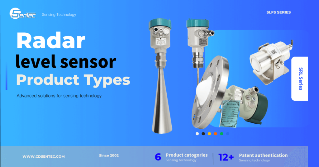
Radar technology choice for bypass installations depends on your specific needs. Guided wave radar (GWR) and non-contact radar (NCR) each bring unique benefits based on installation conditions, process variables, and measurement goals.
Best Uses for Guided Wave Radar Level Transmitter
Guided wave radar works great at measuring interfaces between two liquids, which makes it perfect for tracking oil-water boundaries. This technology can detect both upper level and interface at once when the difference between dielectric constants is greater than 10, with the upper layer having εr<3 and lower layer εr>20.
GWR shows excellent results in bypass installations with turbulent surfaces or foam. Expert analysis shows guided radar handles “challenging conditions such as high temperatures, high pressures, and corrosive environments” without losing accuracy.
Guided wave radar stands out if you need:
Oil/water interface measurement
Reliable readings for products with very low dielectric constant (DC < 1.9) and turbulent surface
Measurements in areas with heavy condensation
Maximum measurement accuracy
Reliable performance with foam present
Benefits of Non-Contact Radar Level Sensors
Non-contact radar transmitters excel where touching the medium creates problems. These devices “deliver reliable and accurate level readings both in liquid and solids, regardless of vessel type, changing process or environmental conditions”.
Non-contact radar proves ideal with:
Long nozzles and viscous products that build up heavily
Very narrow long nozzles under 3 inches (75 mm) wide up to 6.5 ft (2 m) high
Cases where GWR installation isn’t possible
Materials that must stay untouched to prevent contamination
How Dielectric Constant and Vessel Shape Matter
Dielectric constant plays a crucial role in radar measurement success. This property determines the radar signals’ reflection strength from measured surfaces. Higher values create stronger reflections that devices detect easily.
Materials with low dielectric constants (εr<2.8) reflect signals weakly. Most petroleum products range between 1.4≤εr≤4.0, while water-based solutions go beyond εr>10.0. “The percentage of transmitted signal reflected back is directly related to the material’s dielectric constant”.
Vessel shape also affects measurement reliability. Guided wave radar usually beats non-contact radar in narrow vessels because “GWR can maintain its accuracy and sensitivity independently of the pipe”. Tall, small-diameter pipes might work better with NCR since they “have higher tendency of being crooked, which increases the risk of GWR probes coming into contact with the pipe wall”.
Your radar level measurement success in bypass chambers depends on understanding both dielectric properties and installation geometry.
Installation best practices for radar in bypass chambers
The right installation can make all the difference between getting reliable measurements and dealing with constant headaches in radar level measurement bypass chambers. By doing this, engineers can maximize performance and reduce maintenance needs for these specialized setups.
Still pipe and chamber design considerations
The right bypass chamber size matters. The smallest chambers need 2 inches (50.8mm) in diameter, though larger diameters might be needed for fluids that tend to outgas. The best fluid circulation comes from minimal restrictions between vessel and chamber through wide-diameter connections and short piping.
Your chamber length should fit both the measurement span you need and the upper/lower transition zones of the guided wave radar. Insulation plays a vital part as “insulation and heat tracing will minimize temperature changes and prevent condensation, freezing, or solidification of fluids”.
Make sure manufacturers use certified materials for new chambers. Check existing chambers for signs of corrosion, stress, or fatigue around welds.
Probe selection: coaxial, single rigid, or flexible
Large diameter coaxial probes should be your first choice when chamber dimensions allow. These probes give the strongest return signal without an upper dead zone and minimal lower dead zone. They work great in chambers with limited space above and below process connections.
Single rigid probes deliver stronger return signals in metal, small-diameter pipes compared to open applications. Flexible probes excel in longer bypass chambers but need careful installation to avoid wall contact. These work best in chambers 4 inches (100mm) or larger.
Avoiding false echoes and signal loss
False echoes come in two types – random and fixed – and create common challenges during radar installation. Poor positioning near inlets or stirring devices often causes random echoes. Fixed echoes usually happen from wrong installation or obstacles in the tank.
Echo tuning helps in cases where disturbing echoes perform better than surface echoes. The False Echo function lets technicians record false echoes from disturbing objects. This improves measurement reliability even when surface echoes look weaker than false echoes.
Using centering disks and venting options
Centering disks stop probe-to-wall contact that would create false reflections and wrong measurements. Rigid single probes usually need one centering disk at the probe end. Flexible probes might need several disks installed at intervals. Keep at least 3 ft (1m) between disks, with no more than five disks per probe.
Single probe applications under fluid need chamber venting near the top. This removes trapped air or gas that could affect reading accuracy. Venting also helps level manipulation for transmitter verification or chamber drainage.
Replacing legacy systems with radar level transmitters
Industrial facilities commonly use outdated displacer technology to measure levels, despite its major limitations. Radar technology advancements make these mechanical devices prime candidates to upgrade.
Why engineers replace displacers with radar
Several operational challenges push engineers to choose radar alternatives over displacers:
Changes in fluid properties affect measurement accuracy due to density dependence
Maintenance costs rise because moving parts need regular cleaning and replacement
Reading reliability suffers from mechanical vibration and turbulence
Product changes and service require recalibration
Guided wave radar (GWR) technology provides density-independent measurements without moving parts. This reduces maintenance costs and improves measurement accuracy. Radar level measurement stays accurate regardless of pressure and temperature changes—a vital advantage in ever-changing industrial environments.
How to modernize existing chambers
The modernization process for existing displacer installations depends on chamber setup. Side-to-side and side-to-bottom configurations need minimal work. You can remove the displacer electronics and float, then install a radar transmitter with the right flange.
Overhead piping makes top-to-bottom and top-to-side configurations trickier. In spite of that, 90° bent rod segments help install radar without getting pricey pipe rerouting.
The radar transmitter flange must match your chamber type while picking replacement equipment. Manufacturers use both standard ANSI/DIN flanges and proprietary chamber flanges with non-standard diameters.
Setting range values and calibration tips
Engineers can choose from three main options to configure range values:
Zero reference at lower tap – Tank height should match the distance to zero level point with LRV at 0 inches
Match displacer output – Tank height equals probe length with LRV as the distance from probe bottom to lower tap
Match actual tank level – Use correct gage height with LRV as the distance from tank bottom to lower tank connection
Proper venting near the chamber top helps eliminate trapped air that could affect reading accuracy.
Plant engineers often implement radar technology throughout their facilities after seeing its benefits firsthand. The difference in reliability becomes clear right away when you compare old measurement methods to modern radar systems.
Radar level measurement technology saves money in the long run through less maintenance and better process reliability. The original installation might cost more than mechanical alternatives, but this is a big deal as it means that the total ownership cost ends up lower as time goes by. You won’t need to maintain or replace moving parts, which cuts down on regular expenses.
Guided wave radar technology stands out as the best choice for most bypass applications with tough process conditions. It handles temperature changes, pressure shifts, and interface measurement with ease across chemical processing, oil and gas, and water treatment industries of all sizes.
Before you pick your radar system, take time to assess:
Process media characteristics (dielectric constant, viscosity, tendency to foam)
Environmental conditions (temperature ranges, pressure fluctuations, vibration)
Required measurement accuracy and repeatability specifications
Available installation space and existing chamber configurations
The way you install your system makes all the difference in how well it performs. Even the best radar level transmitter won’t give you great results if it’s not installed correctly. Therefore, it’s crucial to work with manufacturer representatives during specification and installation to get the setup just right.
Industrial sectors need more automation these days, and radar level measurement technology is without doubt the most reliable solution for challenging bypass applications. The technology doesn’t get affected by environmental factors, needs minimal maintenance, and provides stable measurements. These benefits make it a better choice than traditional alternatives.
Each application comes with its own challenges. Modern radar systems are flexible enough to handle almost any process requirement. With proper attention to application details and installation methods, radar level measurement works better than anything else in bypass installations that usually cause measurement headaches.
FAQs
Q1. What are the main advantages of radar level measurement in bypass installations? Radar level measurement offers stable readings in turbulent conditions, immunity to temperature and pressure changes, and reduced maintenance due to the absence of moving parts. It provides accurate measurements even in the presence of foam or agitation.
Q2. How does guided wave radar differ from non-contact radar in bypass applications? Guided wave radar excels in applications requiring interface measurement between two liquids and performs well in turbulent or foamy conditions. Non-contact radar is better suited for situations where physical contact with the medium is undesirable or when dealing with long, narrow nozzles.
Q3. What factors should be considered when installing radar level transmitters in bypass chambers? Key considerations include proper chamber sizing, insulation, probe selection (coaxial, single rigid, or flexible), avoiding false echoes, and using centering disks. Venting options near the top of the chamber are also important for submerged single probe applications.
Q4. Why are engineers replacing displacers with radar level transmitters? Engineers opt for radar technology because it offers density-independent measurements, requires less maintenance due to the absence of moving parts, and provides more reliable readings in challenging conditions such as mechanical vibration and turbulence.
Q5. How does the dielectric constant of a material affect radar level measurement? The dielectric constant influences the strength of the radar signal reflection from the measured surface. Materials with higher dielectric constants create stronger reflections, making them easier to detect. For low dielectric constant materials (below 2.8), signal reflection weakens considerably, potentially affecting measurement accuracy.
