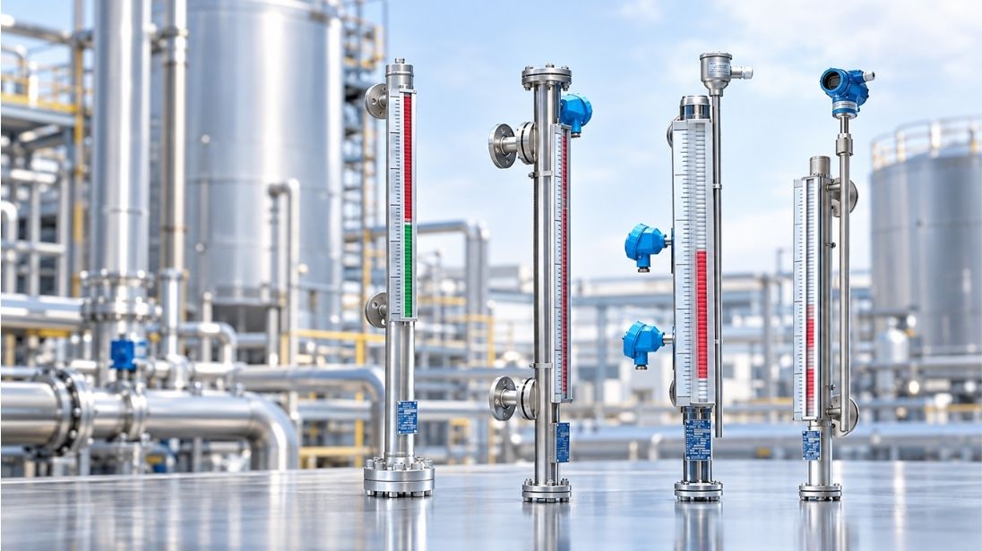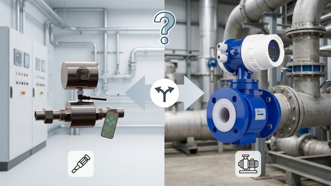
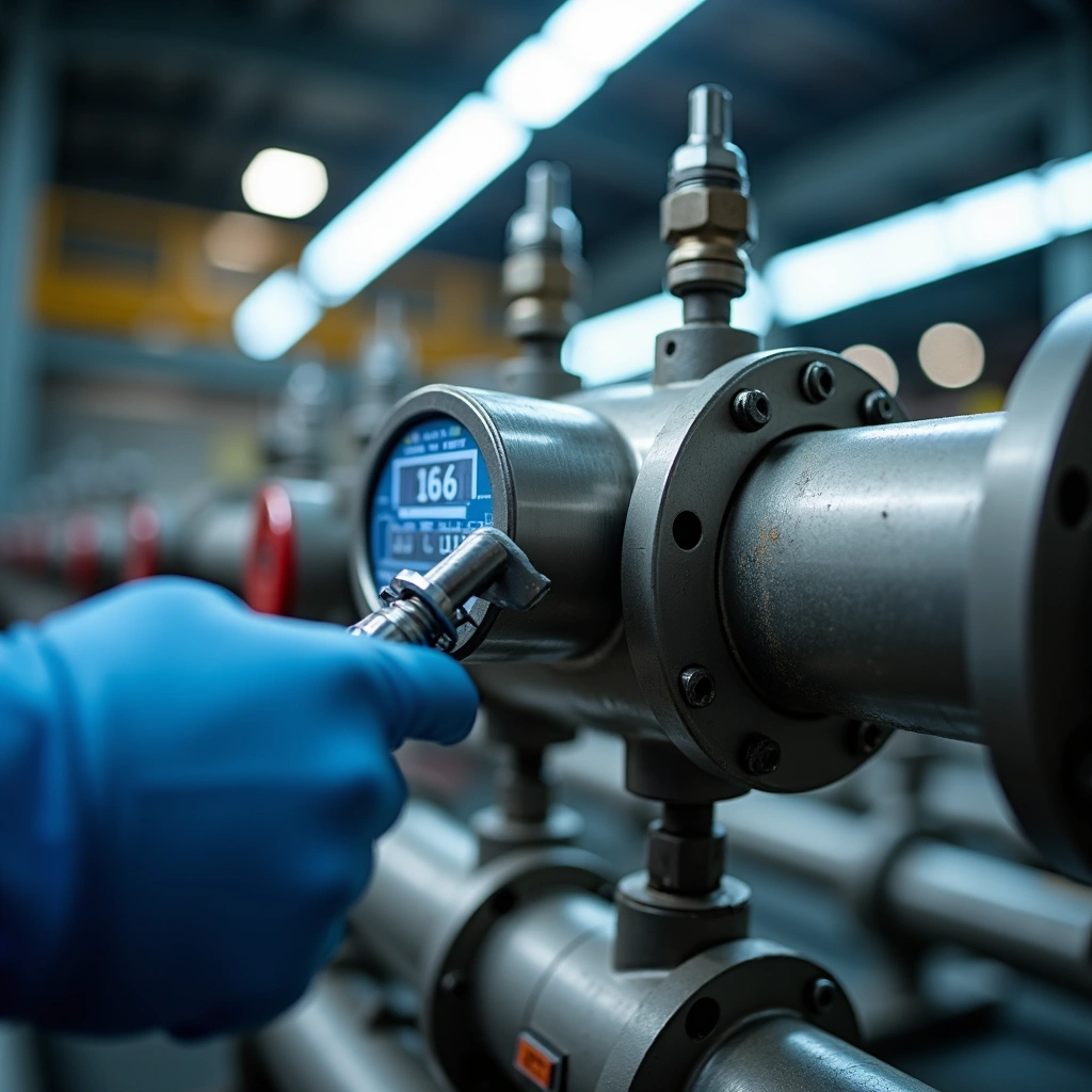
Pressure transmitter maintenance is critical because these instruments are the most commonly used equipment in modern industrial control. Good daily maintenance can extend the life of your products and prevent failures that get pricey. The measuring part must remain leak-free when subjected to upper limit pressures. You need to maintain insulation resistance of at least 20MΩ between terminals. In this piece, we’ll walk you through complete pressure transmitter maintenance procedures. This includes our preventive maintenance checklist for pressure transmitter systems. You’ll learn proper differential pressure transmitter maintenance techniques and routine inspection methods. We’ll also show you how to implement a pressure transmitter preventive maintenance program that works and keeps your operations running smoothly.
Understanding Pressure Transmitter Maintenance Requirements
Why regular maintenance matters for your operations
Pressure transmitters function as nerve endings in industrial process control systems. They convert gas, liquid, or steam pressure into standardized signals for immediate monitoring. Industry data shows that 40% of process control system failures stem from inadequate pressure transmitter maintenance. This statistic alone demonstrates why we can’t treat these devices as “install and forget” components.
Extreme temperatures, corrosion, vibration, and pollution affect transmitter accuracy in harsh industrial conditions. Accuracy drift leads to signal failures, increased costs, and unexpected production stops. Proper maintenance extends equipment reliability and reduces emergency repair costs by 12-18% compared to reactive approaches. Studies show preventive maintenance reduces unplanned downtime by nearly 50%.
Different types of maintenance approaches
Three primary maintenance strategies are available for pressure transmitter maintenance procedures. Corrective maintenance occurs after failures and suits non-critical equipment where interruption is acceptable. This reactive approach proves expensive and dangerous for most applications.
Preventive maintenance involves performing tasks on a set schedule at pre-defined intervals. This proactive approach prevents unexpected breakdowns through routine servicing. Maintenance follows a preventive framework: daily inspection, quarterly calibration, and annual full diagnostics. The method relies on minimal data and fixed schedules. This makes it straightforward to implement.
Predictive maintenance represents a data-driven, condition-based approach that uses sensor data, diagnostics, and analytics. Continuous monitoring of key parameters such as sensor drift, signal noise, and internal temperature can identify early signs of potential issues. Modern transmitters equipped with HART communication protocols help with remote monitoring and diagnostics. Predictive maintenance requires higher investment in digital infrastructure but substantially reduces unnecessary maintenance tasks.
A hybrid approach that combines preventive and predictive strategies optimizes maintenance spend and will give stable operations.
Key components that need attention
Lock-out/tag-out principles must be followed before conducting any pressure transmitter maintenance checklist activities. Cut the power supply, close isolation valves to release system pressure, and place locks on equipment. Appropriate personal protective equipment including safety glasses, resistant gloves, and safety suits prevents contact with hazardous media.
Key components that need attention include the diaphragm (avoid hard object contact to prevent damage), electrical connections and terminals, impulse tubes and pressure ports, grounding systems, and isolation seals. Physical components aside, we must verify that insulation resistance remains at least 20MΩ between terminals. Winter freeze protection measures become important for outdoor installations to prevent volume expansion damage.
Daily and Weekly Inspection Procedures
Visual inspection checklist
Routine patrol inspections are the foundations of pressure transmitter maintenance procedures. Begin with a check of the transmitter housing for cracks, moisture ingress, physical damage or signs of corrosion. All seals and gaskets must remain intact. Compromised seals allow environmental contamination. Check the mounting and support structures to confirm the transmitter remains secured properly.
Nameplates and markings should be clear and accurate since they contain critical calibration and specification data. Check fasteners for looseness that can lead to misalignment or vibration-induced failures[102]. Look for any debris accumulation around the meter or dust buildup on surfaces[102].
Checking instrument readings and displays
Check the instrument indication for any abnormalities and confirm it fluctuates within the specified range[102]. Verify secondary readings in the control room for transmitters without on-site indications[102]. Monitor for signs of drifting readings, fluctuating or noisy signals, or outputs stuck at 4mA or 20mA.
Cleaning and debris removal
Remove debris around the instrument and clean dust from surfaces promptly[102]. Exercise extreme caution when cleaning the diaphragm. Never use sharp or edged tools, screwdrivers or pens. The stainless steel diaphragm measures just a few microns thick. Rinse it with a weak water jet or clean it with compressed air. Damage from denting or notching moves the zero point and distorts output signal linearization. This renders the transmitter unreliable.
Checking connections and fittings
Check electrical connections, terminals and wiring for loose connections or damage. Tighten loose terminal screws to prevent connection failures. Look for errors, leaks or corrosion between the instrument and process interfaces, pressure pipes and valves. Confirm connector contact quality and verify terminal wiring remains firm[102].
Pressure Transmitter Preventive Maintenance Checklist
Monthly zero-point inspection
Transmitters include secondary valves or three-valve/five-valve groups. This makes zero-point inspection convenient and quick. Close the secondary valve and open the exhaust screw to ensure proper zero point. For differential pressure transmitters, open the balance valve and close the high and low pressure valves. Then open the exhaust screw. Verify the transmitter displays a zero reading with no pressure applied. If not, make adjustments through the zero trim function.
Draining and venting procedures
Before removing a transmitter from service, bleed accumulated fluid pressure to achieve a zero energy state. Switch to manual operation and open the equalizing valve. Then initiate drainage through the drain valve. After draining completes, close the drain valve. Verify the transmitter’s differential output shows 100%. These procedures prevent hazardous process fluid ejection during maintenance work.
Impulse tube flushing and cleaning
Purge impulse lines at regular intervals for media that tend to clog. A continuous flow of clean fluid through a purge valve keeps lines clear and allows accurate pressure measurement. The purge restriction must allow just enough flow to prevent plugging without creating pressure drop errors. Purge fluid supply pressure must exceed process pressure at all times. Otherwise process fluid flows backward into the line.
Testing insulation resistance
Use a megohmmeter to measure insulation resistance. Apply DC voltage and measure leakage current. Test voltage selection depends on equipment rating. For 460V to 600V rated equipment, 1000V test voltage is appropriate. Perform tests at standard conductor temperature of 20°C or establish a temperature baseline. Disconnect electronic devices like PLCs and transmitters before testing. This prevents damage from higher than normal voltage.
Checking grounding and wiring
Connect the metal shell to earth so components remain equipotential with ground. This redirects leakage currents and filters power supply interference. When output shows irregular jumps despite constant pressure, check whether the metal shell is grounded. Also check whether shielded cables are grounded.
Winter freeze protection measures
Water that freezes damages sensors. It causes excessive pressure on diaphragm elements and results in permanent distortion. Install heat tracing on impulse lines and transmitter bodies in freezing environments. You can also inject stable emulsified lubricant into the diaphragm cavity. This displaces air and prevents water contact.
Common Failure Modes and How to Prevent Them
Blockage in impulse lines
Blockages create confusing troubleshooting situations where trapped pressure remains even after actual process conditions change. Wax buildup, sludge accumulation, ice formation and condensate blockage obstruct impulse lines. Fluctuating components of differential and static pressures decrease when an impulse line blocks. Trace heating on impulse lines becomes essential in freezing environments, as approximately 60% of trace-heating systems fail to work as designed due to installation problems. Purge impulse lines for media prone to clogging using continuous clean fluid flow [factual keypoints reference].
Corrosion damage prevention
Proper material selection ensures process-wetted parts resist your specific media. Diaphragm seals protect instruments by creating a barrier between corrosive substances and sensing elements. Barrier systems using U-tubes filled with compatible fluids like mineral oil work well for aggressive fluids. Yearly calibrations are recommended practice.
Diaphragm damage
Diaphragm failures result from sustained overpressure, cavitation, pressure spikes, mechanical damage from pointed tools and corrosion. Signs include oil leaking from pressure ports, decaying output signals, sudden signal changes at certain pressures and large zero offset shifts. Diaphragms cannot be repaired once damaged.
Temperature-related problems
Media temperature affects sensing diaphragms and causes zero drift. Mean Time Between Failure decreases by half for every 10°C increase in operating temperature. Capillary lines or diaphragm seals distance transmitters from extreme process temperatures. Steam siphons work for steam applications where traditional accessories prove inadequate.
Leakage problems
Water entering the instrument corrodes internal electronic components. Cable interfaces and sealing rings need regular checks, and aged components require replacement. Fill fluid must remain contained in diaphragm seal systems.
Output signal errors
Outputs stuck at 4mA or 20mA indicate power supply problems, wiring issues or damaged components. Measure raw voltage at zero pressure and full capacity to determine if the sensor responds. Power supply voltage must remain above 12V for proper operation.
Conclusion
Proper pressure transmitter maintenance prevents the 40% of control system failures caused by inadequate upkeep. This complete guide helps you extend equipment life and reduce emergency repair costs by 12-18% while cutting unplanned downtime nearly in half. A combined approach that uses preventive scheduled tasks with predictive monitoring delivers the best results. Start with our maintenance checklist today to keep your operations running smoothly and avoid pricey transmitter failures before they affect production.