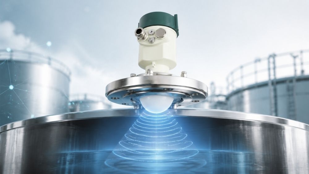
Frequency modulated continuous wave radar technology has reshaped industrial level measurement, yet proper configuration remains a challenge for many operators. Setting up a 76-81 GHz radar level gage requires understanding multiple parameters, from calibration points and deadbands to damping modes and echo learning algorithms. Incorrect settings can lead to unstable readings or complete measurement failures.
Frequency modulated continuous wave fmcw radar systems offer exceptional accuracy when configured correctly. Whether you’re working with liquid tanks or bulk solids applications, understanding how fmcw frequency modulated continuous wave radar parameters interact is everything in reliable operation.
We’ve compiled this FAQ guide to walk you through simple setup parameters, operational modes, advanced calibration techniques, and system diagnostics for 76-81 GHz radar level gages.
Basic Setup and Measurement Parameters for 76-81 GHz Radar Level Gages
How are High Calibration and Low Calibration determined?
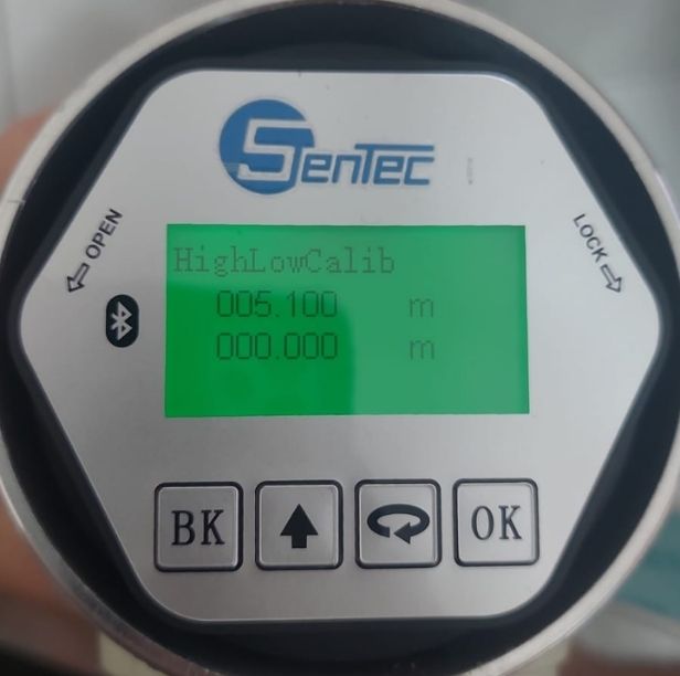
Low Calibration (Low Calib) corresponds to the empty tank reference point, measured as the distance from the sensor lens to the tank bottom. High Calibration (High Calib) marks the full tank level. The numerical difference between these values defines your measurement span using the formula: Low Calib – High Calib.
A 5 m tank example shows how this works: setting High Calib to 0 m and Low Calib to 5 m maps the empty tank to 0 m and the full tank to 5 m. This configuration allows the frequency modulated continuous wave fmcw radar to translate physical distance into meaningful level data.
What is the function of the Measuring Range setting?
The Range setting establishes boundaries for the evaluation zone used by internal algorithms. The radar ignores reflections beyond this limit and filters out spurious signals from outside the measurement area.
Set the range approximately 2 m deeper than your actual tank height, especially when you have conical-bottom vessels. This will give a complete bottom return echo characteristics without signal truncation for the fmcw frequency modulated continuous wave radar. You can adjust range settings locally or remotely via software, HART, or Modbus protocols.
What is Deadband (Blind Zone) and how does it affect readings?
Deadband specifies the near-end physical measurement boundary, with a factory default minimum of 80 mm. The system ignores any signals within this zone to prevent false 100% full readings caused by close-range reflections off nozzles or mounting sockets.
Deadband acts as a protective buffer. The sensor would misinterpret reflections from the installation hardware as actual product level without this zone.
How do measurement unit changes affect probe reading?
Distance unit changes alter only the numerical display on the LCD or mobile interface. They do not modify sensor measurement accuracy, internal calculations, or the 4-20 mA loop current output.
The frequency modulated continuous wave radar performs similar measurements whether you view readings in meters, feet, or inches. The conversion happens at the display layer and leaves the core measurement engine untouched. So you can switch units to match operator priorities or regional standards without recalibrating the instrument.
Operational Modes and Environmental Adaptation in FMCW Radar Systems
What are the different Application Occasions and why avoid Demo Mode?
Application settings configure internal signal filtering and damping for specific process conditions. Each mode tailors the frequency modulated continuous wave radar behavior to match your operating environment:
- Small Vessel: Low damping for rapid filling/emptying rates
- Medium Vessel: Standard damping for general storage tanks
- Large Vessel: High damping for slow, stable output trends
- Agitator: Filters surface turbulence and moving mixer blades
- Demo Mode: Zero-delay response designed for indoor bench testing only
A unit left in Demo Mode during actual operations will cause unstable, erratic level jumps due to unreduced process noise. This setting bypasses all filtering algorithms that suppress environmental interference.
How does Damping Time affect live data during tank operations?
Damping time smoothes output signal transitions caused by liquid surface ripples, splashing, or rapid agitation. You can configure this parameter from 0 to 300 seconds. The factory default is 5 seconds.
Higher damping stabilizes live data and prevents sudden reading jumps without interrupting the fmcw frequency modulated continuous wave radar’s physical measurement cycle. The sensor continues scanning at its fastest interval of 300 milliseconds whatever damping settings you choose. The damping function acts as a mathematical filter on the output signal, not a constraint on measurement frequency.
What is the recommended mounting angle for different applications?
Install the sensor perpendicular to the liquid surface for liquid media. Maximum allowable tilt stays within 3 degrees to maximize signal reflection back to the antenna.
Bulk solids require a different approach. A universal swivel flange angle device points the narrow radar beam (either 3 degrees or 8 degrees depending on antenna type) at the tank discharge cone. This positioning will give optimal echo retrieval from irregular, sloped solid surfaces where perpendicular mounting would scatter the signal.
Advanced Calibration, Echo Learning, and Offset Guidelines
What is Sensor Offset and can it be manually modified?
Distance Offset adjusts the physical reference point of the gage. The factory reference sits at the center of the antenna lens and establishes the zero point for all distance calculations.
We discourage manual alteration of sensor offset. Changing this value shifts all derivative variables, including measured distance, calculated level, and 4-20 mA output signals. The factory adjusts this parameter during manufacturing using precision test fixtures. Field modifications introduce measurement errors that cascade through the whole system.
What is False Echo Learning and when is it required?
False Echo Learning generates a baseline threshold curve to map and suppress static background interference caused by internal vessel structures. Pipes, ladders, heating coils, and other fixed obstacles create persistent reflections that can confuse the frequency modulated continuous wave radar’s tracking algorithms.
The function offers two modes: Area Learning maps interference within a specified distance interval, while Full-range Learning scans the entire measurement zone. But this remains an advanced parameter. Do not initiate false echo learning unless fixed structural obstacles interfere with normal tracking. Unnecessary learning cycles can suppress legitimate product echoes in applications with variable fill patterns.
Understanding the Echo Graph screen lines and figures
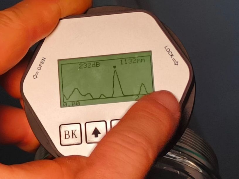
The echo diagnostic interface provides live signal analysis through numerical readouts and visual plots. Top values display return signal amplitude in decibels (dB) with the current measured distance in meters. Bottom values indicate the start and end distance limits of the active evaluation window set by your range configuration.
Visual lines plot the live return echo curve against the baseline threshold curve. Strong echoes appear as peaks rising above the threshold line. The fmcw frequency modulated continuous wave radar tracks the highest amplitude peak within the evaluation window and filters out weaker signals below the threshold. This graphical representation helps diagnose signal quality issues, verify false echo learning effectiveness, and confirm proper antenna alignment during commissioning.
Electrical Configuration, Communication Protocols, and System Diagnostics
How does Current Simulation work in frequency modulated continuous wave radar?
Current Simulation locks the analog output to a user-defined current between 4 mA and 20 mA. The factory default is 4 mA. Technicians can verify loop wiring, PLC/DCS input channels and receiving displays without altering actual process level conditions with this testing mode.
The frequency modulated continuous wave fmcw radar maintains this fixed output until you exit the simulation menu. Active measurement output restores at that point. You can verify complete signal chain integrity from the sensor terminals to the control room without disrupting operations.
How does Fault Current Output behave during signal loss?
The loop current responds according to your configured Fault Current setting at the time a measurement error occurs, such as loss of echo (error code 0001):
- No Change: Holds the last valid current value
- 22 mA: Outputs high fault alarm signal
- 3.6 mA: Outputs low fault alarm signal
This programmable fault behavior integrates with your facility’s alarm philosophy. You can distinguish between process conditions and instrument failures.
Configuring Bus Addresses, Modbus Baud Rates, and Bluetooth options
Modbus baud rates default to 9600 but scale up to 115200 for faster data transfer. Communication addresses range from 0 to 32 for HART protocol and 1 to 127 for Modbus networks. Multi-drop configurations with many gages on a single bus become possible.
Units equipped with Bluetooth 5.0 operate within approximately 12 m range. Standard Android mobile apps provide wireless configuration access for safe field diagnostics. You won’t need to climb tanks or open junction boxes.
What happens during a Factory Reset?
Factory Reset (Restore Factory) reverts user settings to default factory configurations. This function proves valuable at times improper parameter modifications prevent normal measurement operation. Sensor offset and factory calibration measures remain preserved. The fmcw frequency modulated continuous wave radar’s core measurement integrity stays protected while problematic user changes get cleared.
Conclusion
Frequency modulated continuous wave radar technology delivers exceptional accuracy when you configure it right. We’ve covered calibration points, damping modes and echo learning algorithms. You now have the knowledge to set up your 76-81 GHz radar level gage for reliable operation. Begin with simple parameters and verify your settings through the echo graph. Avoid common pitfalls like Demo Mode in live applications. Proper configuration will give you stable measurements and prevent expensive downtime.