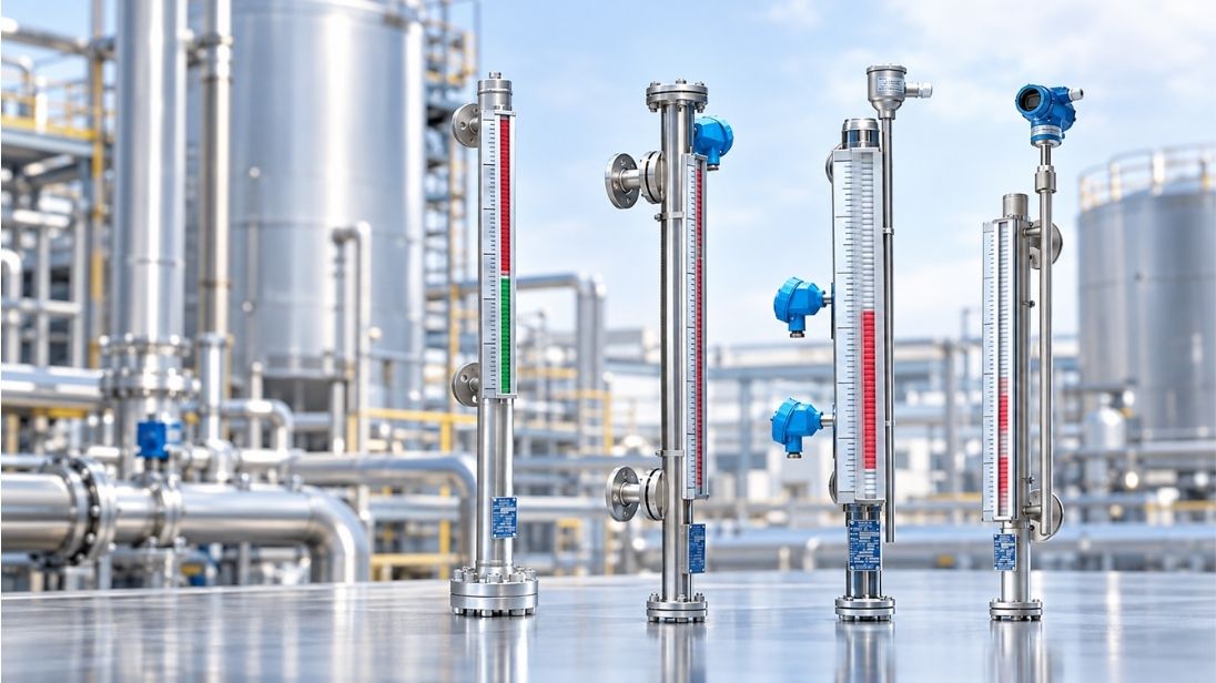

Over 70% of level measurement issues in oil & gas arise from neglected maintenance or improper float calibration. The magnetic gauge offers a proven solution to this challenge. These resilient instruments can withstand temperatures up to 400°C and pressures up to 300 bar. They are ideal for handling corrosive or hazardous materials. A refinery in southeast China showed this reliability when they replaced glass sight glasses with magnetic level gauges on six diesel storage tanks and recorded zero leak events for 12 consecutive months. In this piece, we’ll walk you through the operating principles of magnetic level indicators and explore practical applications including hydropower plant monitoring and liquid-liquid interface measurement. We’ll also detail maintenance strategies that keep your magnetic liquid level gauge systems running safely and accurately.
Operating Principle of Magnetic Level Gauges
Simple Mounting and Operation
Magnetic level gauges operate on the communicating vessels principle. The chamber mounts externally to the process vessel through side flanges, one at the top and one at the bottom in vertical orientation. Process fluid flows between the vessel and chamber through these connections. So the liquid level inside the chamber matches the vessel level at all times.
A float containing permanent magnets moves with the rising and falling liquid inside the chamber. The float construction uses materials selected for process conditions: 316 stainless steel or titanium for standard applications, with specialized alloys available for corrosive environments. The float remains 70 percent submerged in the process fluid during normal operation. This submersion ratio provides stability and maintains magnetic coupling strength through the chamber wall.
The chamber itself must be constructed from non-magnetic materials to allow magnetic field penetration. Wall thickness affects coupling strength. Thicker walls can weaken the magnetic interaction between internal float magnets and external indicators.
Visual Indication Mechanism
External visual indicators mount on the outside of the chamber and remain isolated from process fluid. Each indicator contains a series of bi-color flags, red on one side and white (or silver) on the other. These flags rotate on ceramic and stainless steel bearing surfaces.
The float’s magnetic field penetrates the chamber wall as the float moves with changing liquid level. This field couples with alignment magnets embedded in each flag. The magnetic interaction rotates each flag 180 degrees when the float passes. The rotation reveals one color below the liquid surface and the opposite color above it. This creates a clear visual boundary that tracks the actual level.
An alternative to rotating flags is the shuttle indicator (also called a follower). This design uses a bright red magnetic element that moves along a graduated scale inside a hermetically-sealed tube. The shuttle provides higher resolution than flags but may be more susceptible to decoupling during severe turbulence.
Signal Transmission and Control Integration
Magnetic level indicators serve as mounting platforms for electronic transmitters beyond visual indication. Reed switch chains mount along the chamber length. The float opens or closes switches in sequence as it passes each reed contact. The total number of connected resistors produces a proportional resistance value and generates a continuous 4-20 mA output signal.
Magnetostrictive transmitters provide higher accuracy, within ±1 millimeter. A current pulse travels down an internal waveguide. The magnetic field generates a torsional stress wave that returns to the transmitter at the float position. Time-of-flight calculation determines exact float position. These transmitters output standardized signals including 4-20 mA, HART, Modbus, or Foundation Fieldbus protocols.
External magnetic switches can be added at fixed positions for discrete high or low level alarms. These switches activate without breaching the pressure boundary and maintain process containment while providing control interlock capability.
Practical Application Scenarios
Hydropower Plant Bearing Oil Sump Level Monitoring
Rolling element bearings in hydroelectric generators require precise lubrication levels to prevent premature failure. Bearing manufacturer data shows that 250 parts per million water contamination in lubricating oil reduces bearing life by a factor of four. External magnetic level indicators mounted on bearing oil sumps provide continuous visual monitoring without electrical power requirements in high-electromagnetic interference environments common near generator windings.
The magnetic liquid level gauge tracks oil volume fluctuations caused by thermal expansion during operation and consumption through seal leakage. Proper oil level maintenance prevents both starvation conditions that lead to metal-to-metal contact and overfilling that causes churning and accelerates oxidation rates. Installations include 4-20 mA transmitter outputs connected to distributed control systems for remote monitoring and low-level alarms that trigger automatic makeup oil systems.
Immiscible Liquid-Liquid Interface Measurement
Oil-water separators in petroleum production and refining facilities rely on interface detection between immiscible phases. The lighter hydrocarbon layer floats above the denser water phase due to specific gravity differences. Magnetic level gauges designed for interface service use calibrated floats that position themselves at the boundary between the two liquids based on Archimedes’ principle.
A float sized for the intermediate density between oil and water remains suspended at the interface. Produced fluids enter the separator and settle, and the magnetic level indicator tracks interface position changes. This measurement controls automated discharge valves that remove the water phase while retaining hydrocarbons. Magnetostrictive transmitters paired with visual indicators provide redundant measurement, especially when you have emulsion layers that form at the interface and complicate single-technology solutions.
Maintenance and Maintenance Strategies
Manual Overhaul and Inspection Procedure
Clean and inspect magnetic level indicators at least once a year. Process severity may require more frequent maintenance. The gauge requires removal from service if mud or other floating substances gather in the lower portion of the instrument.
Close the process valves to isolate the chamber. Close the lower valve first and then the top valve. The vent connection should be opened to equalize pressure with atmosphere slowly. Drain off any remaining liquid in a way that meets plant requirements. Standard magnetic level indicators have a ½-inch vent and drain plug in the top and bottom of the float chamber to clean and remove process fluid.
Remove the flange on the bottom of the gauge. Be careful not to allow the float to drop on the floor, as this can damage the float and magnet assembly. Clean the inside wall of the chamber with a bottle brush or scrubbing tool. Replace the float with the arrows in the “Up” position. Use a new gasket, replace the bottom flange and tighten all fasteners to the proper torque.
Non-Disassembly In-Line Flushing System
Connect the gauge to solvent or steam lines if you want to clean the magnetic level gauge periodically without stopping service or removing the drain flanges or floats. Magnetic level gauges stay in best condition if the drain plug is opened from time to time to wash out any deposits and prevent settlement in the bypass tube.
Key Specification Checklist for Selection
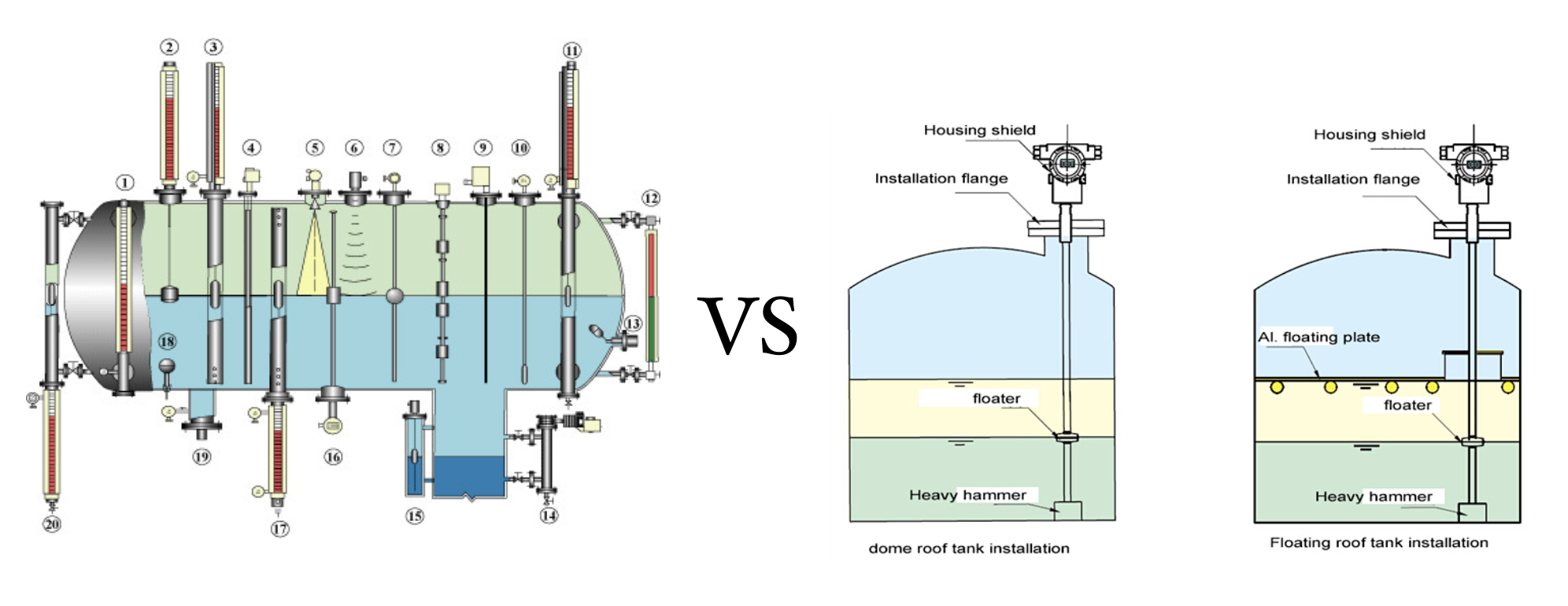
To specify a magnetic level indicator, you just need to match gauge design to actual process conditions. Start with liquid properties: specific gravity determines float buoyancy. The float must be less dense than the liquid at the lowest operating temperature. Low-density hydrocarbons require special floats.
Operating temperature and pressure determine chamber wall thickness, gasket material and magnet selection. Standard chambers handle full vacuum to 4,000 psi and temperatures from -320°F to 1,000°F. Minimum specific gravity can reach 0.39.
Match chamber and float materials to the medium. Stainless steel 316/316L handles general chemicals and water. Corrosive chemicals require 316L with PTFE lining or Hastelloy. High-temperature steam applications just need 316L or alloy steel rated to 540°C. Cryogenic liquids require 316L with frost extension.
Specify center-to-center distance between process connections, which defines measuring range. Standard single-piece lengths reach 5,000-5,600 mm. Process connections come as NPT, socket weld, or flanged from ½-inch to 3 inches. Flanges follow ANSI B16.5 or EN 1092-1 standards.
Your final configuration depends on whether you need local indication only, continuous transmitter output or alarm switches.
Conclusion
Magnetic level gauges deliver reliable measurement in conditions where other technologies fail. Proper specification and routine maintenance protect your investment and ensure continuous operation. Match float materials and chamber ratings to your process conditions, then establish a maintenance schedule that has annual inspections and periodic flushing. Follow these practices and your magnetic level indicators will provide decades of accurate liquid level measurement in even the most demanding applications.